Hardware layout and configuration UM2198
20/69 DocID030511 Rev 1
A green LED LD10 lights up in one of these cases:
• Power switch (U18) is ON and the STM32H743I-EVAL board works as a USB host
• V
BUS
is powered by another USB host when the STM32H743I-EVAL board works as a
USB device.
The red LED LD8 lights up when an overcurrent occurs (I
VBUS
> 500 mA).
Note:1 The STM32H743I-EVAL board should be powered by an external power supply when using
OTG function.
Note:2 JP2 and SB50 must be removed when using USB OTG FS as mentioned in Table 11.
8.10 USB OTG2 HS and FS
The STM32H743I-EVAL Evaluation board supports USB OTG2:
• High-speed communication through a USB Micro-AB connector (CN14), USB
high-speed PHY (U13) for high-speed function
• Full-speed communication through another USB Micro-AB connector (CN16)
The Evaluation board can be powered by these USB connectors (CN14 or CN16) at 5 V DC
with 500 mA current limitation.
As several OTG2 FS signals are shared with the OTG2 HS ULPI bus and USART1, some
PCB reworks are needed when using OTG2 FS (CN16) as shown in Table 9.
A USB power switch (U14) is also connected on V
BUS
and provides power to either CN14
(with SB27 and SB30 closed and SB28 and SB29 open) or CN16 (with SB28 and SB29
closed and SB27 and SB30 open).
Green LED LD5 (for CN14) or LD7 (for CN16) lights up in one of these cases:
• Power switch (U14) is ON and the STM32H743I-EVAL board works as a USB host.
• V
BUS
is powered by another USB host when the STM32H743I-EVAL board works as a
USB device.
The red LED LD6 lights up when an overcurrent occurs (I
VBUS
> 500 mA).
Note: The STM32H743I-EVAL board should be powered by an external power supply when using
OTG function.
8.11 RS232
Communication through RS232 is supported by the D-type, 9-pins connector CN2, which is
connected to the USART1 of the STM32H743XI on the STM32H743I-EVAL Evaluation
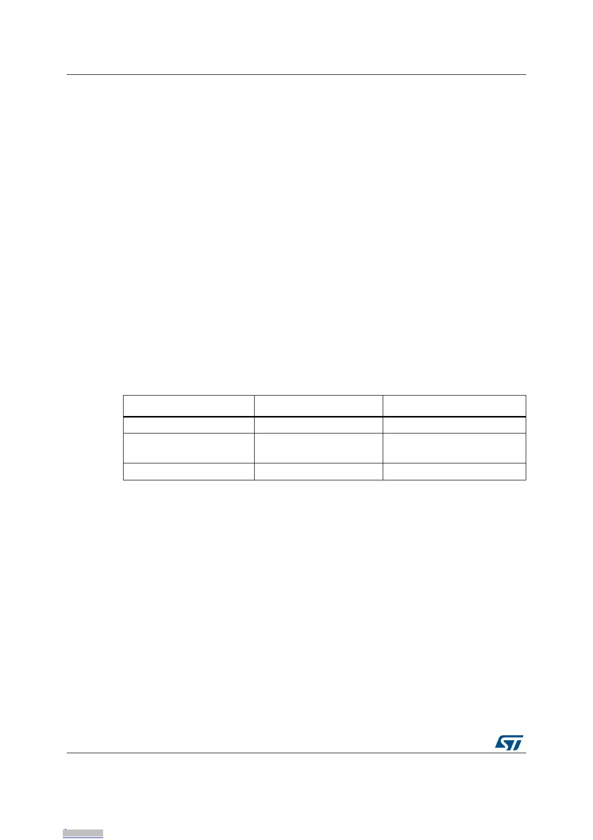
Table 9. USB OTG2 and USART1 function configuration
Function Mount Remove
OTG2 HS-CN14 (Default) R104,R105,SB27,SB30 R254,SB48,SB28,SB29
OTG2 FS-CN16
R254,SB48,SB28,SB29
SB47,SB49
R104,R105,SB27,SB30,
SB46,SB51
USART1 (Default) SB46,SB51 SB47,SB49
Downloaded from Arrow.com.Downloaded from Arrow.com.Downloaded from Arrow.com.Downloaded from Arrow.com.Downloaded from Arrow.com.Downloaded from Arrow.com.Downloaded from Arrow.com.Downloaded from Arrow.com.Downloaded from Arrow.com.Downloaded from Arrow.com.Downloaded from Arrow.com.Downloaded from Arrow.com.Downloaded from Arrow.com.Downloaded from Arrow.com.Downloaded from Arrow.com.Downloaded from Arrow.com.Downloaded from Arrow.com.Downloaded from Arrow.com.Downloaded from Arrow.com.Downloaded from Arrow.com.

 Loading...


