EasyManua.ls Logo

ST STM32MP157F-EV1 User Manual

ST STM32MP157F-EV1
61 pages
To Next Page IconTo Next Page
Page #1 background imageLoading...
Page #1 background image
Introduction
The STM32MP157F-EV1 Evaluation board is designed as a complete demonstration and development platform for
STMicroelectronics Arm
®
-based dual Cortex
®
A7 32 bits and Cortex
®
M4 32 bits MPUs in the STM32MP1 Series. It leverages
the capabilities of increased-frequency 800 MHz STM32MP1 Series microprocessors for the user to develop applications, using
STM32 MPU OpenSTLinux Distribution software for the main processor, and STM32CubeMP1 software for the co-processor. It
includes an ST-LINK embedded debug tool, LEDs, push-buttons, one joystick, 1-Gbps Ethernet, CAN FD, one USB OTG Micro-
AB connector, four USB Host Type-A connectors, LCD display with touch panel, camera, stereo headset jack with analog
microphone input, four digital microphones, one SPDIF Rx/Tx, smartcard, microSD
card, and eMMC, NOR and NAND Flash
memories.
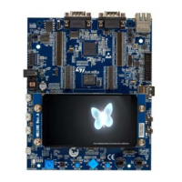
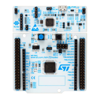
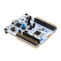
STM32MP157F-EV1, shown in Figure 1 and Figure 2, is used as the reference design for user application development,
although it is not considered as final application.
To expand the functionality of the STM32MP157F-EV1 Evaluation board, two GPIO expansion connectors are also available for
motor control and Raspberry Pi
®
shields.
An ST-LINK/V2-1 is integrated on the board, as embedded in-circuit debugger and programmer for the STM32 MPU and the
USB Virtual COM port bridge.
Figure 1. STM32MP157F-EV1 top view
Figure 2. STM32MP157F-EV1 bottom view
Pictures are not contractual.
Evaluation board with increased-frequency 800 MHz STM32MP157 MPU
UM2648
User manual
UM2648 - Rev 1 - June 2020
For further information contact your local STMicroelectronics sales office.
www.st.com

Table of Contents

Question and Answer IconNeed help?

Do you have a question about the ST STM32MP157F-EV1 and is the answer not in the manual?

ST STM32MP157F-EV1 Specifications

General IconGeneral
BrandST
ModelSTM32MP157F-EV1
CategoryMotherboard
LanguageEnglish

Summary

Introduction

Features

STM32MP157 Microprocessor Details

Core processor details and package type.

Memory and Storage Specifications

DDR3L, eMMC, NAND, Flash memory.

Display, Audio, and Microphone Features

TFT display, audio codec, microphones.

User Input Controls

Buttons, joystick.

On-board ST-LINK/V2-1 Debugger

Integrated debugger and programmer.

Ordering Information

Available Product List

Product codes and references.

Product Marking Conventions

Evaluation tool marking details.

Part Number Codification

Part number system explanation.

Development Environment

Development System Requirements

Prerequisites for development.

Supported Development Toolchains

Supported IDEs and compilers.

On-board Demonstration Software

Preloaded software for demonstration.

Conventions

Jumper and Switch Conventions

Definitions for jumper and solder bridge states.

Delivery Recommendations

Hardware Layout and Configuration

Hardware Block Diagram

Diagram of the board's functional blocks.

Board Component Overview

Visual identification of main components.

Power Supply Management

5V Power Supply Input

Primary power input and indicator.

Platform Power Distribution Tree

Power distribution diagram.

STPMIC1 Power Management IC

Power management IC details.

Clock Sources

Low-Speed External (LSE) Clock

Low-speed external clock.

High-Speed External (HSE) Clock

High-speed external clock.

Reset Sources

User Buttons and LEDs Configuration

Button and LED I/O Mapping

Mapping I/O to buttons and LEDs.

Physical User Input Devices

User Buttons and Joystick Details

Details on physical input controls.

Boot Options

Boot Mode Switch Configuration

Switch settings for boot sources.

Embedded ST-LINK/V2-1

Embedded ST-LINK/V2-1

ST-LINK USB Connector Pinout

Pinout of the ST-LINK USB connector.

ST-LINK Driver Installation Guide

Guide for installing ST-LINK drivers.

ST-LINK/V2-1 Firmware Upgrade

TRACE Mictor-38 Connector

TRACE Connector HW Configuration

Configuration for TRACE signals.

JTAG Connector

JTAG Connector Pinout

Pinout of the JTAG connector.

DDR3L Memory Details

eMMC Interface Configuration

eMMC I/O Interface HW Configuration

HW configuration for eMMC.

NAND Flash Memory Details

NAND I/O Interface HW Configuration

HW configuration for NAND.

Quad-SPI NOR Flash Memory

Quad-SPI I/O Interface HW Configuration

HW configuration for Quad-SPI.

microSD Card

SD Card Interface I/O Configuration

I/O configuration for SD card.

Audio

Audio Codec Interface Details

Interface details for audio codec.

Digital Microphone Specifications

Details on MEMS digital microphones.

Audio

Analog Mic and Headset Jack

Headset jack with microphone input.

Digital Microphone Jumper Settings

Jumper settings for microphone config.

Audio Speaker Output Jack

SPDIF Input and Output Connectors

DSI LCD

DSI LCD Interface I/O Configuration

I/O configuration for LCD.

Camera

Camera Interface I/O Configuration

I/O configuration for camera.

1 Gbps Ethernet

Ethernet RGMII Interface I/O Configuration

I/O configuration for Ethernet.

USB OTG HS

USB OTG HS Interface I/O Configuration

I/O configuration for USB OTG.

USB Host

USB Host Interface I/O Configuration

I/O configuration for USB Host.

RS-232 Port

RS-232 Port

RS-232 Interface HW Configuration

HW configuration for RS-232.

RS-232 I/O Usage Restrictions

Limitations on RS-232 use.

CAN FD

CAN FD Operating Voltage

Voltage for CAN FD transceiver.

CAN FD Interface I/O Configuration

I/O configuration for CAN FD.

Smartcard

Smartcard Interface HW Configuration

HW configuration for smartcard.

ADC/DAC

ADC/DAC I/O Interface Configuration

I/O configuration for ADC/DAC.

Fast ADC Channel Configuration

Configuration for fast ADC channels.

Slow ADC Channel Configuration

Configuration for slow ADC channels.

ADC/DAC Usage Limitations

Usage limitations for ADC/DAC.

I2C_EXT Connector

I2C_EXT I/O Interface Configuration

HW configuration for I2C_EXT.

MFX MCU

MFX I/O Expander HW Configuration

HW configuration for MFX interface.

Motor Control

Motor Control I/O Assignment

Assignment of motor control terminals and functions.

Motor Control

Motor Control Limitations

Usage limitations for motor control.

GPIO Expansion Connector

RGB LTDC Connector

MB1262/CN11 Connector Pinout

RGB LTDC Connector Limitations

STM32MP157F-EV1 Evaluation Board Information

Board Identification Details

Product identification details.

Product Revision History

History of board revisions.

Known Product Limitations

List of known issues.

STM32MP157F-EV1 Jumper Summary

STM32MP157F-EV1 I/O Assignment

FCC and ISED Canada Compliance Statements

FCC Compliance Statement Details

FCC compliance rules and statements.

ISED Canada Compliance Statement

ISED Canada compliance rules.

CE Conformity

CE Conformity Warning

Warning about Class A product and radio interference.

Safety Instructions

Revision History

Related product manuals