Table 39. ADC/DAC connectors JP7/JP8/JP9/JP10/JP1
1 pinout
Signal name Pin Pin Signal name
ADC/DAC 1 2 GND
6.24.4 Limitations
Due to the sharing of some I/Os of STM32MP157FAA1 by multiple peripherals, the following limitations apply in
using the PMOD button features:
The fast ADC ANA0/ANA1 and slow ADC PF12 may not be operated simultaneously with the motor
control function.
6.25 I2C_EXT connector
I2C_EXT connector MB1262/CN13 may be connected to I
2
C
bus daughterboard. CN13 connector pin 5 is
connected to 3V3, meaning that the external module must be compliant with 3V3.
MFX_GPIO0 of MFX MCU provides EXT_RESET.
6.25.1 I2C_EXT I/O interface
Table 40. HW configuration for the I2C_EXT interface
I/O Bridge
Setting
(1)
Comment
PA11
MB1262/
SB51
ON PA11, used as I2C5_SCL, is connected to EXT_SCL
OFF
PA11 is not connected to EXT_SCL
P
A11 may be connected to the GPIO expansion connector through MB1262/
SB52
PA12
MB1262/
SB54
ON PA12, used as I2C5_SDA, is connected to EXT_SDA
OFF
PA12 is not connected to EXT_SDA
P
A12 may be connected to the GPIO expansion connector through MB1262/
SB55
MFX_GPIO0 - - Connected to EXT_RESET
1.
Default configuration is shown in bold
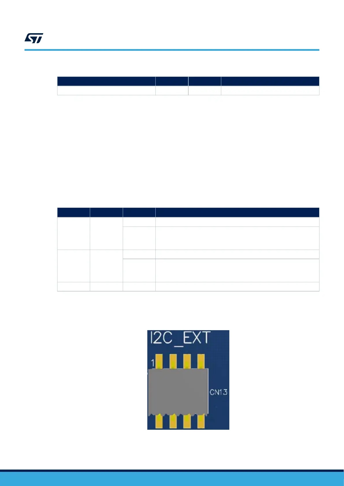
Figure 23 shows the I2C_EXT connector pinout MB1262/CN13.
Figure 23. I2C_EXT connector pinout MB1262/CN13
Table 41 describes the I2C_EXT connector pinout
MB1262/CN13.
UM2648
I2C_EXT connector
UM2648 - Rev 1
page 36/61