I/O Configuration
USB_DP2 USB_DP2
USB_DM2 USB_DM2
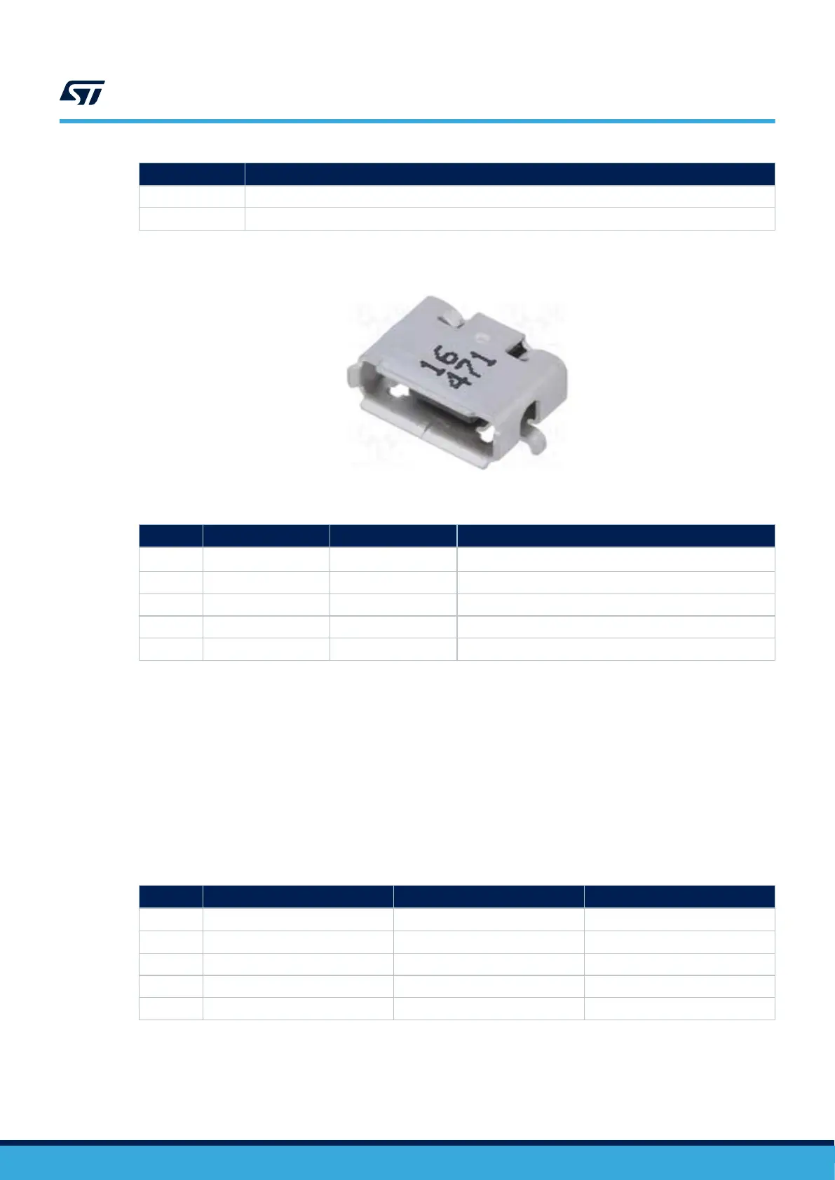
Figure 16. USB OTG
Micro-AB connector MB1262/CN16
Table 29. USB OTG Micro-AB connector pinout MB1262/CN16
Pin CN16 Pin name Signal name Function
1 VBUS OTG VBUS
V
BUS
supply and sensing
2 D- DM USB_DM2
3 D+ DP USB_DP2
4 ID ID ID
5 GND VBUS GND
6.20 USB host
The STM32MP157F-EV1 board provides 4 USB host port (2 dual USB Type-A connectors MB1262/CN18 and
CN20) by means of USB Hub USB2514B-AEZC. The USB2514B has a full power management for each USB
Host port. The default configuration of USB2514B is done in HW, thus I
2
C is not needed by default. However, if
required for a specific application, I
2
C may be accessed through MB1262/SB71 and SB68 to I2C2 as described in
Table 30.
6.20.1 USB Host interface
Table 30 describes the I/O configuration for the USB Host interface.
T
able 30. I/O configuration for the USB Host interface
I/O SB Setting
Configuration
(1)
PH5 MB1262/SB71 OFF PH5 is not used as I2C2_SDA
PH4 MB1262/SB68 OFF PH4 is not used as I2C2_SCL
PD10 - - SUB_NRST
USB_DP1 - - USB1_P
USB_DM1 - - USB1_N
1.
Default configuration in bold
UM2648
USB host
UM2648 - Rev 1
page 30/61