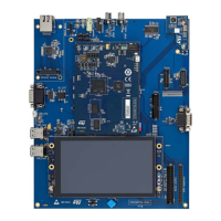
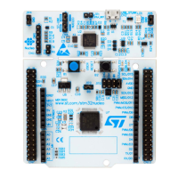
Motor control connector CN22 STM32MP157FAA1 microprocessor
Terminal Terminal name
Port
name
Function Alternate function
Board configurations to
enable motor control
24 GND - - - -
25 5V - - - -
26 Heatsink Temp. PF11 ADC_1_IN2 SAI_2_SD_B
Close MB1262/SB70
Open MB1262
/SB8 and SB69
27 PFC Sync PE0 TIM4_ETR SAI_2_MCLK_A
Close MB1262/SB53
Open MB1262
/SB7
28 3V3 - - - -
29 PFC PWM PB8 TIM4_CH3 DCMI_D6 Close MB1262/SB24
30 GND - - - -
31 Encoder A PH10 TIM5_CH1 DCMI_D1 Close MB1262/SB28
32 GND - - - -
33 Encoder B PH11 TIM5_CH2 DCMI_D2 Close MB1262/SB30
34 Encoder Index PH12 TIM5_CH3 DCMI_D3 Close MB1262/SB26
Figure 24. Motor control connector
MB1262/CN22
6.27.2 Limitations
Due to the sharing of some I/Os of STM32MP157FAA1 by multiple peripherals, the following limitations apply in
using the motor control features:
The motor control may not be operated simultaneously with the camera, audio codec, CAN and GPIO
expansion (GPIO6, 7 and 12).
6.28 GPIO 40-pin expansion connector
A 2×20-pin, 2.54 mm, GPIO connector is implemented on MB1262/CN21.
28 pins are
GPIOs, 8 are GND, 2× 5V DC and 2× 3V3 DC are provided on this connector.
This GPIO 40-pin expansion connector has a Raspberry Pi
®
shield support capability.
Figure 25. MB1262/CN21 connector
Please note the pin1 position that is on the bottom right on MB1262/CN21.
Table 45 describes the MB12622/CN21 connector pinout.
UM2648
GPIO 40-pin expansion connector
UM2648 - Rev 1
page 39/61

 Loading...


