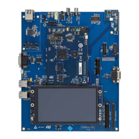
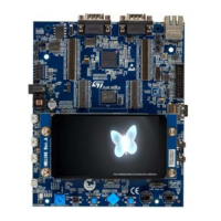
Figure 14. SPDIF input
MB1262/CN1 and output MB1262/CN2 connectors
6.15.6 I/O restriction to other features
Due to the sharing of some I/Os of STM32MP157FAA1 by multiple peripherals, the following limitations apply in
using the audio features:
The SAI audio codec must not be operated simultaneously with expansion connector MB1262/CN21. The
MEMS DFSDM must not be operated simultaneously with DFSDM of EXT MEMS module MB1262/CN8.
6.16 DSI LCD
Through the MB1262/CN19 connector, a DSI LCD mounted on a daughterboard MB1230 is provided. MB1230 is
a 5.5" TFT 720*1280 pixels with LED backlight,
MIPI DSI
SM
interface and capacitive touch panel based on
RK055AHD042-CT module embedding the LCD driver IC RM68200 and a touch screen controller GT9147.
3V3 and VIN supply MB1230:
• 3V3: for the LCD module (VDD_LCD and VIO_LCD) and touch screen
• VIN: for the LED backlight of the LCD
6.16.1 DSI LCD interface
MB1230 is connected to the STM32MP157FAA1 through the DSI interface, I
2
C to control the GT9147, and
LCD_BL_CTRL. LCD_INT signal is connected to MFX.
The I
2
C is I2C2 that is shared with all the peripherals: audio codec, MFX, RGB
LTDC, camera, and USB Hub. The
GT9147 I
2
C address is 0xBB.
Table 24 describes the I/O configuration for the LCD interface.
Table 24. I/O configuration for the LCD interface
I/O Configuration
PH4 I2C2_SCL
PH5 I2C2_SDA
DSI_D0P DSI_D0_P is used as MIPI-DSI data Lane 0 positive
DSI_D0N DSI_D0_N is used as MIPI-DSI data Lane 0 negative
UM2648
DSI LCD
UM2648 - Rev 1
page 26/61

 Loading...


