Those four digital microphones support two stereo inputs connected either to the audio codec or, by default,
connected on two DFSDM odd channels of
STM32MP157FAA1: DFSDM_DATA1 and DFSDM_DATA3
synchronized on DFSDM_CKOUT.
The STM32MP157FAA1 DFSDM interface is shared among the four embedded digital microphones and the
extension module on connector MB1262/CN8.
Table 21 describes the HW configuration for the digital microphones.
Table 21. HW configuration for the digital microphones
Jumpers HW Setting
Configuration
(1)
MB1262/JP1
U1/U3 stereo
output
selection
JP1[1-2] Connected to codec DMICDAT2
JP1[2-3] Connected to STM32MP157FAA1 DFSDM_DATA3
MB1262/JP2
U2/U4 stereo
output
selection
JP2[1-2] Connected to codec DMICDAT1
JP2[2-3] Connected to STM32MP157FAA1 DFSDM_DATA1
MB1262/JP3
U1/U2/U3/U4
CLK selection
JP3[1-2] Connected to STM32MP157FAA1DFSDM_CKOUT
JP3[2-3] Connected to codec DMICCLK
MB1262/JP4
U1/U2/U3/U4
VDD
selection
JP4[1-2] 3V3
JP1[2-3] Codec MICBIAS1
1.
Default configuration in bold
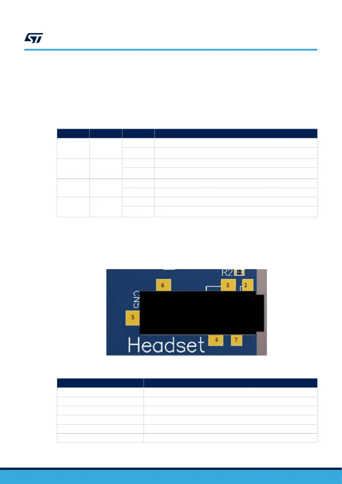
6.15.3 Analog microphone and audio jack headphone
A headset including an analog microphone and a stereo headphone may be connected to the black 3.5 mm
headset jack MB1262
/CN5.
Figure 12. Audio jack connector MB1262/CN5
Table 22. Audio jack connector pinout
MB1262/CN5
Pin Board function
2 MIC_IN
3 GND
4 OUT_RIGHT
5 N/A
6 OUT_LEFT
7 N/A
UM2648
Audio
UM2648 - Rev 1
page 24/61