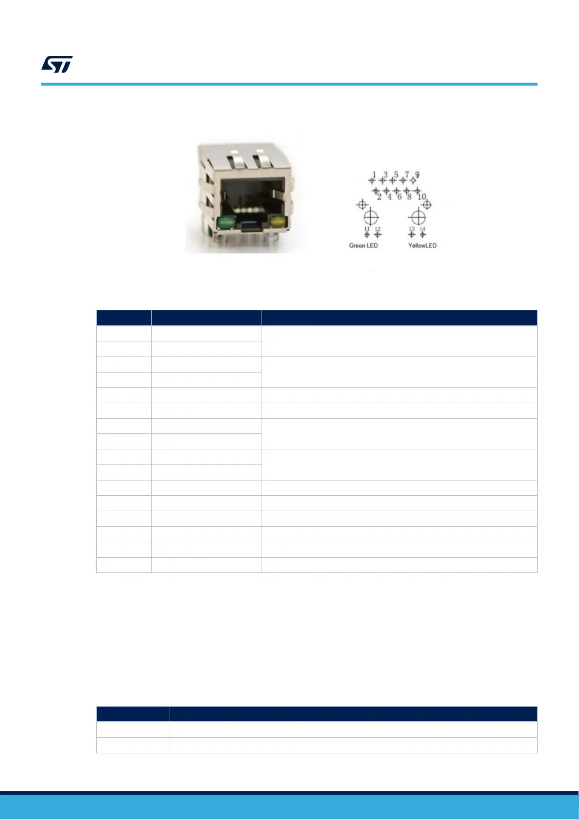
Figure 15. Ethernet connector MB1262/CN3
Table 27. Ethernet connector pinout MB1262/CN3
Pin number Pin name Function
1 TX1+
First Bidirectional pair to transmit and receive data
2 TX1-
3 TX2+
Second Bidirectional pair to transmit and receive data
4 TX2-
5 CT1 Common connected to GND
6 CT2 Common connected to GND
7 TX3+
Third Bidirectional pair to transmit and receive data
8 TX3-
9 TX4+
Fourth Bidirectional pair to transmit and receive data
10 TX4-
11 GA Green Led anode
12 GC Green Led cathode
13 YA Yellow Led anode
14 YC Yellow Led cathode
15 GND GND
16 GND GND
6.19 USB OTG HS
The STM32MP157F-EV1 board supports USB OTG high-speed communication via a USB Micro-AB connector
MB1262/CN16. OTG V
BUS
supply is managed by the STPMIC1. MB1262/LD2 turns green when USB OTG
connection is established.
6.19.1 USB OTG interface
Table 28 describes the I/O configuration for the USB OTG interface.
T
able 28. I/O configuration for the USB OTG interface
I/O Configuration
PA10 OTG_ID line detection
OTG_VBUS OTG_VBUS sensing
UM2648
USB OTG HS
UM2648 - Rev 1
page 29/61