Do you have a question about the ST STM32F072 and is the answer not in the manual?
Details on evaluation sample ('ES' or 'E') product marking on the device.
Explains the meaning of the product codification for the discovery kit.
Lists the operating systems and cable needed for development.
Specifies the recommended software tools for development.
Information about the preloaded demo software and its source code.
Defines jumper and solder bridge states (ON/OFF) used in the document.
Describes the integrated ST-LINK/V2 debugger and its usage modes.
Details how to connect the ST-LINK/V2 for on-board programming.
Explains connecting ST-LINK/V2 to an external STM32 application.
Covers power supply options and selection on the discovery board.
Describes the function and connections of LEDs and pushbuttons.
Details linear touch sensor, touch keys, and USB device functionality.
Explains BOOT0 pin configuration and the embedded USB bootloader.
Covers the MEMS gyroscope and extension/EEPROM connectors.
Details the configuration of OSC clock sources for the MCU.
Explains the function and states of various solder bridges on the board.
Describes the male headers P1 and P2 for connecting to external boards.
Provides a detailed mapping of MCU pins to board functions.
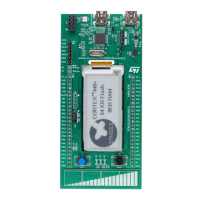
The STM32F072 Discovery kit, also known as the 32F072BDISCOVERY, is a comprehensive evaluation tool designed to help users explore the full capabilities of the STM32F0 Series microcontrollers and develop their applications. It is built around an STM32F072RBT6 microcontroller, which is based on the Arm Cortex-M0 processor and features 128 Kbytes of Flash memory and 16 Kbytes of SRAM in an LQFP64 package.
The primary function of the STM32F072 Discovery kit is to provide a platform for programming, debugging, and testing applications for the STM32F072RBT6 microcontroller. It integrates an ST-LINK/V2 embedded debug tool interface, which allows for in-circuit programming and debugging of the on-board MCU or an external STM32 application. The kit supports Serial Wire Debug (SWD) for STM32 devices.
The board includes a variety of peripherals to facilitate diverse application development. For motion sensing, it incorporates an I3G4250D ST MEMS motion sensor, a 3-axis digital output gyroscope. User interaction is enabled through six LEDs (one red/green for USB communication, one red for 3.3 V power on, and four user-configurable LEDs in red, orange, green, and blue) and two push-buttons (one for user input and one for reset).
For human interface applications, the kit features a linear touch sensor, which can be configured as a 3-position linear touch sensor or four individual touch keys. This allows for the development of touch-sensitive interfaces.
Connectivity options include a USB Mini-B connector for USB FS (Full Speed) communication, enabling the board to act as a USB device (e.g., a joystick or mouse). An RF EEPROM connector is also provided for connecting an RF EEPROM daughterboard, supporting applications involving dynamic NFC tags.
The board offers flexible power supply options, allowing it to be powered via the USB bus from a host PC or an external 5 V supply voltage. It also provides 3 V and 5 V power outputs for external applications, with a consumption limit of 100 mA.
The STM32F072 Discovery kit is designed for ease of use, making it suitable for both beginners and experienced developers.
The design of the STM32F072 Discovery kit includes features that aid in troubleshooting and customization.
| Brand | ST |
|---|---|
| Model | STM32F072 |
| Category | Microcontrollers |
| Language | English |


 Loading...