10.3 MCU voltage selection 1V8/3V3
The STM32H5 Nucleo-144 board offers the possibility to supply the STM32H5 microcontroller with 1.8 or 3.3 V.
JP4 is used to select the VDD_MCU power level:
• JP4 jumper must be fitted on [1-2] to supply the MCU with 3V3
• JP4 jumper must be fitted on [2-3] to supply the MCU with 1V8
10.4 Current consumption measurement (IDD)
The JP5 jumper, labeled IDD, is used to measure the
STM32H5 microcontroller consumption by removing the
jumper and by connecting an ammeter:
• JP5 must be ON when STM32H5 is powered with VDD (default)
• If JP5 is OFF, an ammeter must be connected to measure the STM32H5 current. If there is no ammeter,
the STM32H5 is not powered.
10.5 Virtual COM port (VCP): LPUART1/USART3
The STM32H5 Nucleo-144 board offers the flexibility to connect the LPUART1 or the USART3 interface to the
STLINK-V3EC, or to the ST morpho and ARDUINO
®
Uno V3 connectors.
The selection is done by setting the related solder bridges (refer to Table 12 and Table 13 below).
By default, the serial interface USART3 (PD8/PD9) that supports the bootloader is connected and directly
available as a Virtual COM port of a PC connected to the STLINK-V3EC USB Type-C
®
connector (CN1).
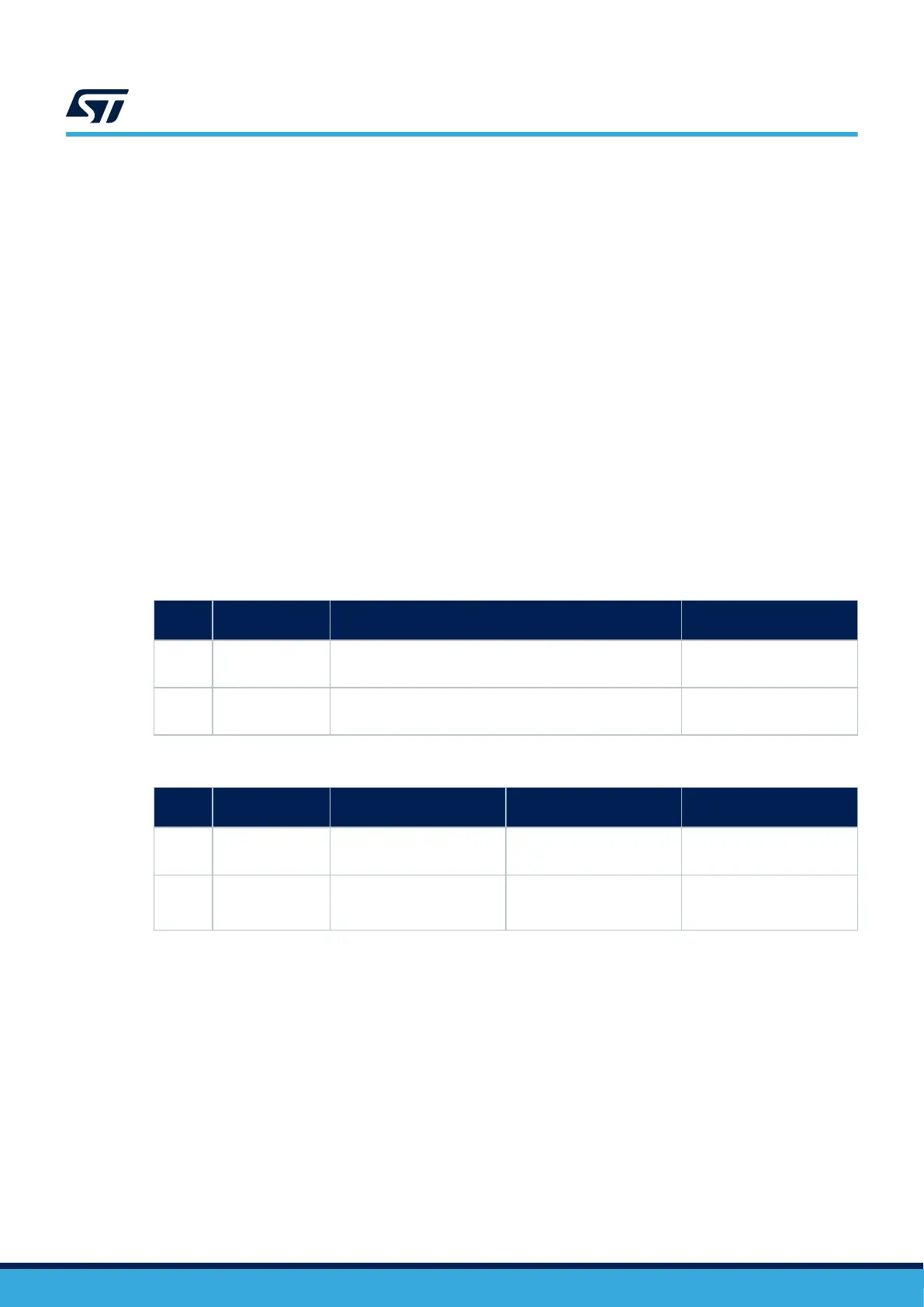
Table 12. USART3 connection
Pin
name
Definition Virtual COM port (default configuration) ST morpho connection
PD8 USART3 TX
SB24 ON
SB13, SB15, and SB23 OFF
SB13 ON
SB23 and SB24 OFF
PD9 USART3 RX
SB18 ON
SB40, SB65, and SB75 OFF
SB75 ON
SB18 and SB65 OFF
Table 13. LPUART1 connection
Pin
name
Definition
Virtual COM port (default
configuration)
ARDUINO
®
D0 and D1
ST morpho connection
PB6 LPUART1 TX
SB15 and SB23 ON
SB14, SB24 OFF
SB14 and SB24 ON
SB15 and SB23 OFF
SB14 and SB15 OFF
PB7 LPUART1 RX
SB40 and SB65ON
SB18 and SB63 OFF
SB18 and SB63 ON
SB40 and SB65 OFF
SB40 and SB63 OFF
By default:
• Serial communication between the target MCU and ST-LINK MCU is enabled on USART3 because this
interface supports the Bootloader mode.
• Serial communication between the target MCU, ARDUINO
®
Uno V3, and ST morpho connectors is
enabled on LPUART1, not to interfere with the VCP interface.
UM3115
MCU voltage selection 1V8/3V3
UM3115 - Rev 2
page 21/44