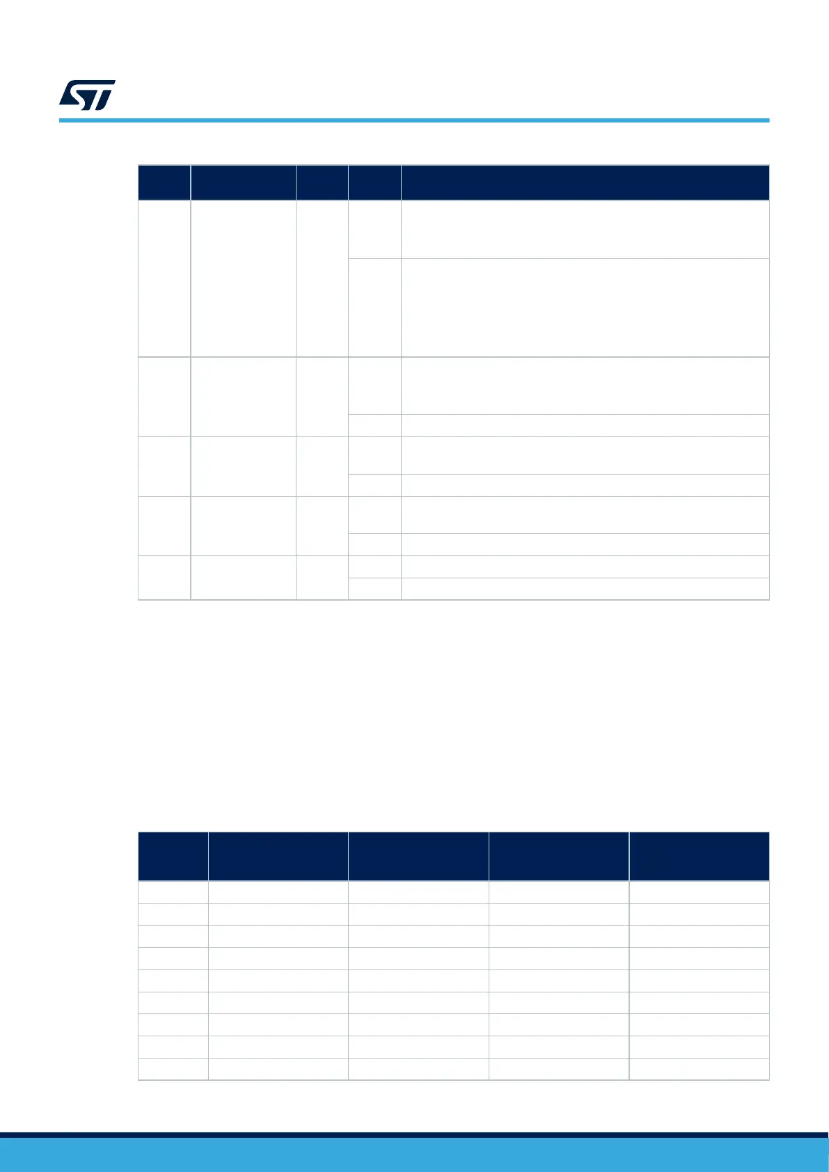
Table 15. Hardware configuration for the UCPD feature
Pin
name
Function
Solder
Bridge
State
(1)
Description
PB13
UCPD_CC1 SB29
ON
PB13 is connected to the USB Type-C
®
port protection and used as
UCPD_CC1. (SB6 and SB12 must be OFF).
If SB6 is ON, thus the protection on the CC1 line is bypassed
OFF
PB13 can be used as:
• GPIO on ST morpho connector (CN12)
– (SB12 must be OFF)
• I2S_CK signal on the Zio connector (CN7)
– (SB12 must be ON).
PB14 UCPD_CC2
SB30
ON
PB14 is connected to the USB Type-C
®
port protection and used as
UCPD_CC2. (SB5 must be OFF).
If SB5 is ON, the protection on the CC2 line is bypassed
OFF PB13 can be used as a GPIO on the ST morpho connector (CN12)
PG7 UCPD_FLT SB74
ON
PG7 is connected to the USB Type-C
®
port protection and used as
overvoltage fault reporting to the MCU.
OFF PB13 can be used as a GPIO on the ST morpho connector (CN12)
PA9 UCPD_DBn SB31
ON
PA9 is connected to the USB Type-C
®
port protection and is used
as a dead battery feature
OFF PA9 can be used as a GPIO on the ST morpho connector (CN12)
PA4 VBUS_SENSE SB56
ON PA4 is used as the VBUS_SENSE signal
OFF PA4 can be used as a GPIO on the ST morpho connector (CN11)
1. The default configuration is in bold.
10.7
Ethernet
The STM32H5 Nucleo-144 board supports 10M/100M Ethernet communication by a PHY LAN8742A-CZ-TR
(U15) and RJ45 connector (CN14). Ethernet PHY is connected to the STM32H5 series microcontroller via the
RMII interface. The PHY RMII_REF_CLK generates the 50 MHz clock for the STM32H5 series microcontroller.
Note: Make sure that JP6 is ON when using Ethernet.
Note: Ethernet PHY LAN8742A must be set in power-down mode (in this mode, the Ethernet PHY reference clock
turns off) to achieve the expected low-power mode current. This is done by configuring the Ethernet PHY basic
control register (at address
0x00) bit 11 (power down) to '1'. SB58 can also be OFF to get the same effect.
Table 16. Ethernet pin configuration
Pin name
Function
Conflict with Zio
connector signal
Configuration when
using Ethernet
Configuration when
using ST Zio or ST
morpho connector
PA1 RMII reference clock - SB58 ON SB58 OFF
PA2 RMII MDIO - SB69 ON SB69 OFF
PC1 RMII MDC - SB62 ON SB62 OFF
PA7 RMII RX data valid - SB38 ON SB38 OFF
PC4 RMII RXD0 - SB42 ON SB42 OFF
PC5 RMII RXD1 - SB36 ON SB36 OFF
PG11 RMII TX enable - SB34 ON SB34 OFF
PG13 RXII TXD0 - SB37 ON SB37 OFF
PB15 RMII TXD1 I2S_A_SD JP6 ON JP6 OFF
UM3115
Ethernet
UM3115 - Rev 2
page 23/44