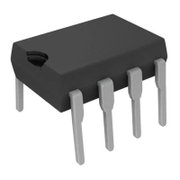
Figure 20 : Latched Shutdown.
D95IN350
BIAS
+
-
EA
R
+
OSC
2N
3905
2N
3903
1mA
R
R
2R
1
2
8
4
SCR must be selected for a holding current of less than 0.5mA at T
A(min)
.
The simple two transistor circuit can be used in place of the SCR as shown. All resistors are 10K.
5
D95IN351
+
-
EA
R
i
+
1mA
R
d
R
2R
5
C
f
R
f
1
2
From V
O
2.5V
+
-
EA
R
P
+
1mA
R
d
R
2R
5
C
f
R
f
1
2
From V
O
2.5V
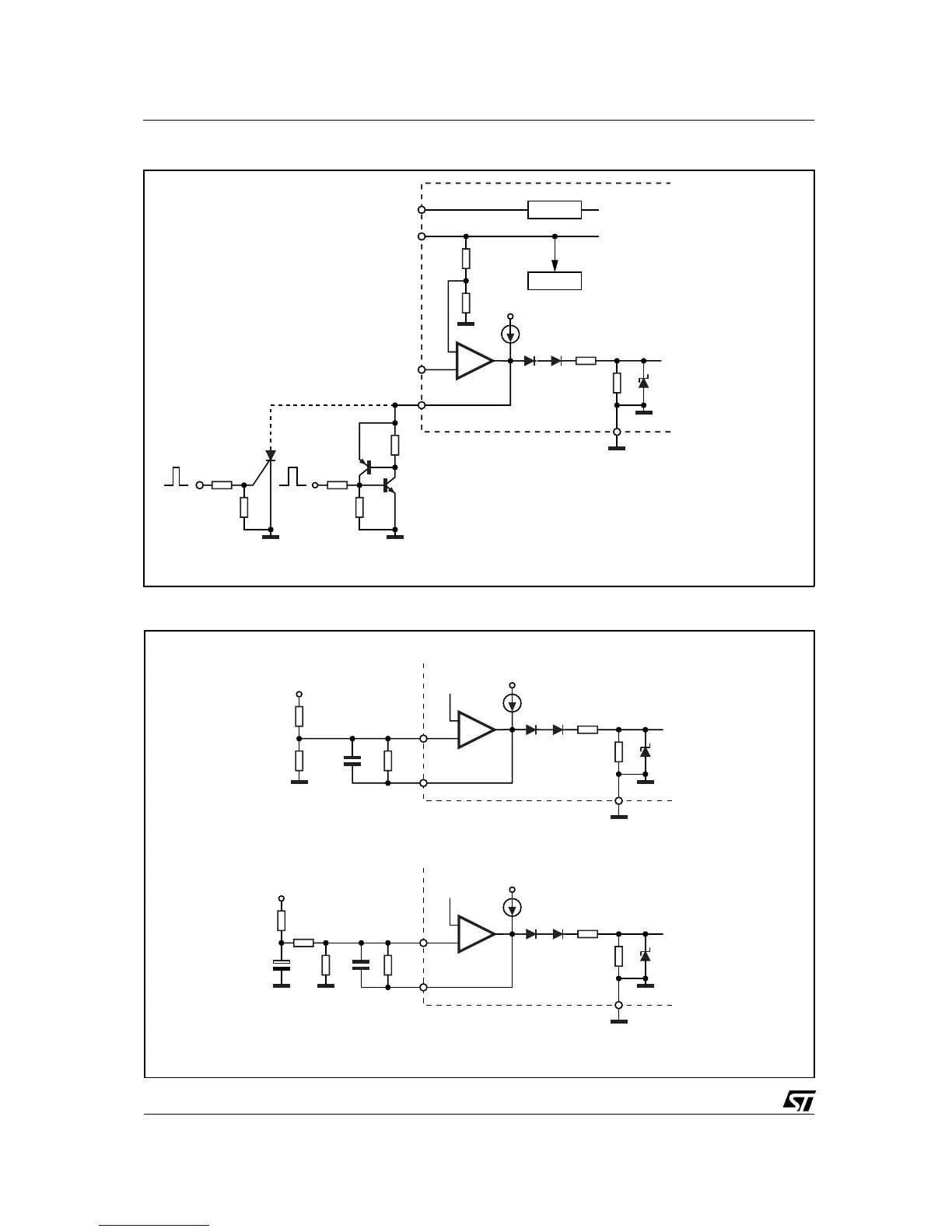
Error Amp compensation circuit for stabilizing any current-mode topology except
for boost and flyback converters operating with continuous inductor current.
C
P
R
i
Error Amp compensation circuit for stabilizing current-mode boost and flyback
topologies operating with continuous inductor current.
Figure 21: Error Amplifier Compensation
UC2842B/3B/4B/5B - UC3842B/3B/4B/5B
10/15