SECTION TWO – Heater Installation
PP
PP
rr
rr
ee
ee
ss
ss
ss
ss
uu
uu
rr
rr
ee
ee
SS
SS
ww
ww
ii
ii
tt
tt
cc
cc
hh
hh
SS
SS
ee
ee
tt
tt
tt
tt
ii
ii
nn
nn
gg
gg
ss
ss
::
::
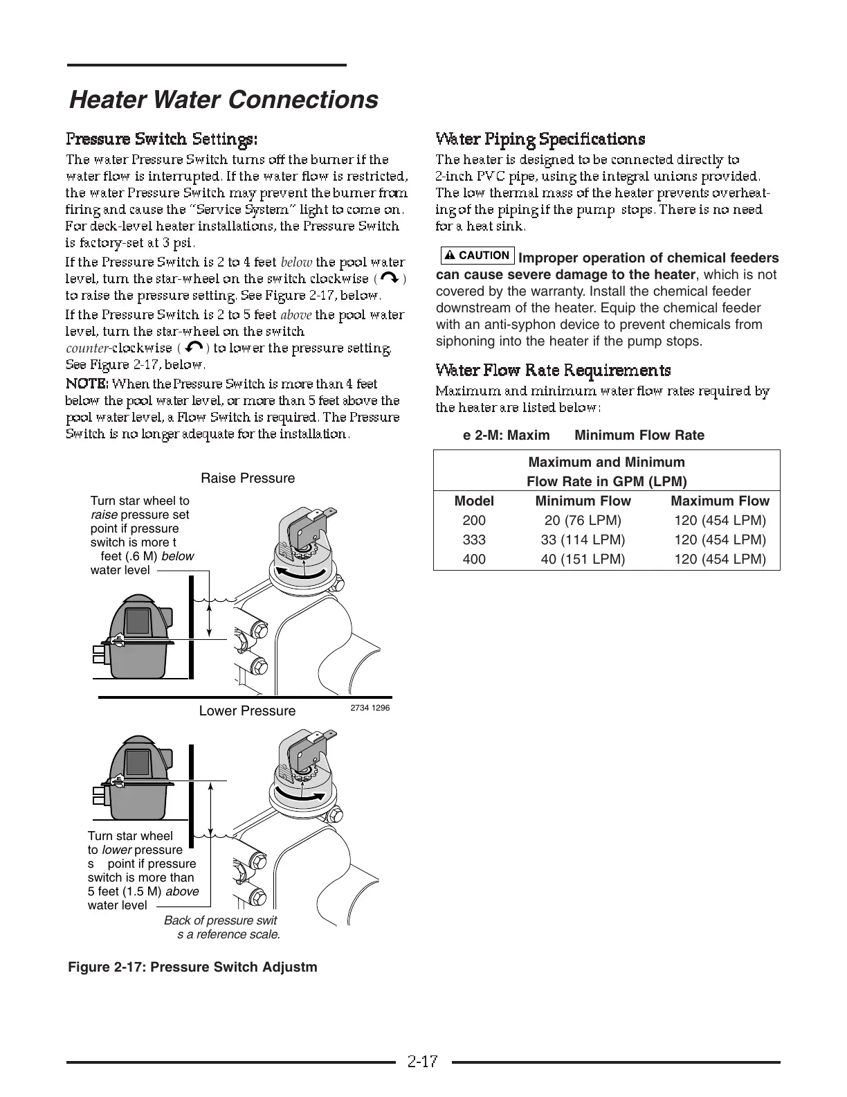
The water Pressure Switch turns off the burner if the
water flow is interrupted. If the water flow is restricted,
the water Pressure Switch may prevent the burner from
firing and cause the “Service System” light to come on.
For deck-level heater installations, the Pressure Switch
is factory-set at 3 psi.
If the Pressure Switch is 2 to 4 feet
below
the pool water
level, turn the star-wheel on the switch clockwise
()
to raise the pressure setting. See Figure 2-17, below.
If the Pressure Switch is 2 to 5 feet
above
the pool water
level, turn the star-wheel on the switch
counter
-clockwise
()
to lower the pressure setting.
See Figure 2-17, below.
NN
NN
OO
OO
TT
TT
EE
EE
::
::
When the Pressure Switch is more than 4 feet
below the pool water level, or more than 5 feet above the
pool water level, a Flow Switch is required. The Pressure
Switch is no longer adequate for the installation.
WW
WW
aa
aa
tt
tt
ee
ee
rr
rr
PP
PP
ii
ii
pp
pp
ii
ii
nn
nn
gg
gg
SS
SS
pp
pp
ee
ee
cc
cc
ii
ii
ff
ff
ii
ii
cc
cc
aa
aa
tt
tt
ii
ii
oo
oo
nn
nn
ss
ss
The heater is designed to be connected directly to
2-inch PVC pipe, using the integral unions provided.
The low thermal mass of the heater prevents overheat-
ing of the piping if the pump stops. There is no need
for a heat sink.
Improper operation of chemical feeders
can cause severe damage to the heater, which is not
covered by the warranty. Install the chemical feeder
downstream of the heater. Equip the chemical feeder
with an anti-syphon device to prevent chemicals from
siphoning into the heater if the pump stops.
WW
WW
aa
aa
tt
tt
ee
ee
rr
rr
FF
FF
ll
ll
oo
oo
ww
ww
RR
RR
aa
aa
tt
tt
ee
ee
RR
RR
ee
ee
qq
qq
uu
uu
ii
ii
rr
rr
ee
ee
mm
mm
ee
ee
nn
nn
tt
tt
ss
ss
Maximum and minimum water flow rates require d b y
the heater are listed below:
2-17
Heater Water Connections
Figure 2-17: Pressure Switch Adjustment
Table 2-M: Maximum/Minimum Flow Rate
Maximum and Minimum
Flow Rate in GPM (LPM)
Model Minimum Flow Maximum Flow
200 20 (76 LPM) 120 (454 LPM)
333 33 (114 LPM) 120 (454 LPM)
400 40 (151 LPM) 120 (454 LPM)