SECTION TWO – Heater Installation
WW
WW
ii
ii
nn
nn
tt
tt
ee
ee
rr
rr
ii
ii
zz
zz
ii
ii
nn
nn
gg
gg
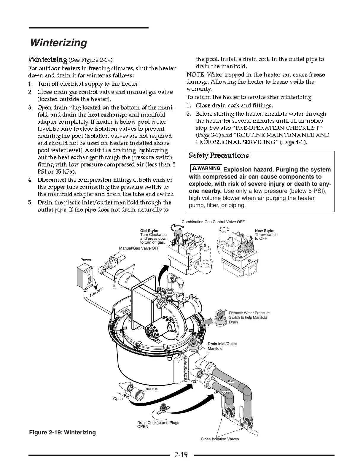
(See Figure 2-19)
For outdoor heaters in freezing climates, shut the heater
down and drain it for winter as follows:
1. Turn off electrical supply to the heater.
2. Close main gas control valve and manual gas valve
(located outside the heater).
3. Open drain plug located on the bottom of the mani-
fold, and drain the heat exchanger and manifold
adapter completely. If heater is below pool water
level, be sure to close isolation valves to prevent
draining the pool (isolation valves are not required
and should not be used on heaters installed above
pool water level). Assist the draining by blowing
out the heat exchanger through the pressure switch
fitting with low pressure compressed air (less than 5
PSI or 35 kPa).
4. Disconnect the compression fittings at both ends of
the copper tube connecting the pressure switch to
the manifold adapter and drain the tube and switch.
5. Drain the plastic inlet/outlet manifold through the
outlet pipe. If the pipe does not drain naturally to
the pool, install a drain cock in the outlet pipe to
drain the manifold.
NN
NN
OO
OO
TT
TT
EE
EE
::
::
Water trapped in the heater can cause freeze
damage. Allowing the heater to freeze voids the
warranty.
To return the heater to service after winterizing:
1. Close drain cock and fittings.
2. Before starting the heater, c irculate water through
the heater for several minutes until all air noises
stop. See also “PRE-OPERATION CHECKLIST”
(Page 3-1) and “ROUTINE MAINTENANCE AND
PROFESSIONAL SERVICING” (Page 4-1).
2-19
Winterizing
to turn off gas.
Figure 2-19: Winterizing
SS
SS
aa
aa
ff
ff
ee
ee
tt
tt
yy
yy
PP
PP
rr
rr
ee
ee
cc
cc
aa
aa
uu
uu
tt
tt
ii
ii
oo
oo
nn
nn
ss
ss
::
::
Explosion hazard. Purging the system
with compressed air can cause components to
explode, with risk of severe injury or death to any-
one nearby. Use only a low pressure (below 5 PSI),
high volume blower when air purging the heater,
pump, filter, or piping.