SECTION FOUR – Routine Maintenance and Professional Servicing
NN
NN
OO
OO
TT
TT
EE
EE
::
::
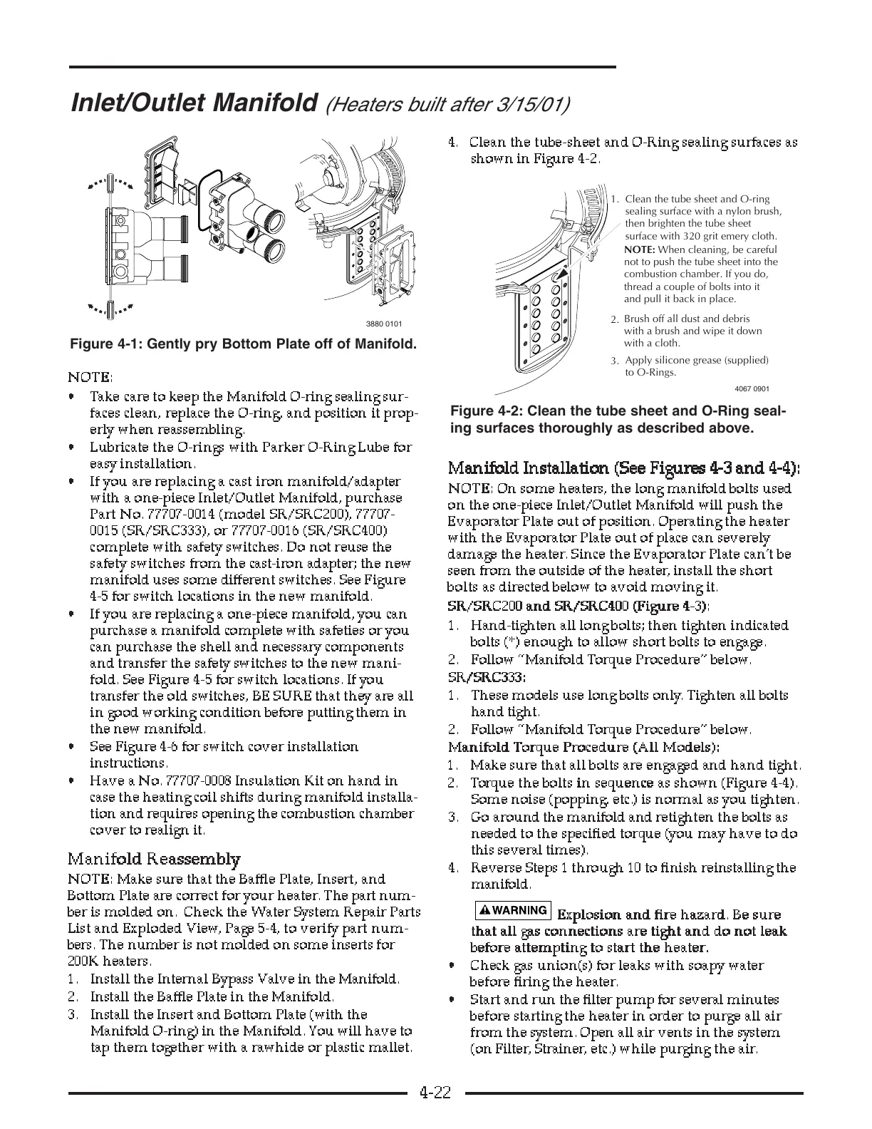
• Take care to keep the Manifold O-ring sealing sur-
faces clean, replace the O-ring, and position it prop-
erly when reassembling.
• Lubricate the O-rings with Parker O-Ring Lube for
easy installation.
• If you are replacing a cast iron manifold/adapter
with a one-piece Inlet/Outlet Manifold, purchase
Part No. 77707-0014 (model SR/SRC200), 77707-
0015 (SR/SRC333), or 77707-0016 (SR/SRC400)
complete with safety switches. Do not reuse the
safety switches from the cast-iron adapter; the new
manifold uses some different switches. See Figure
4-5 for switch locations in the new manifold.
• If you are replacing a one-piece manifold, you can
purchase a manifold complete with safeties or you
can purchase the shell and necessary components
and transfer the safety switches to the new mani-
fold. See Figure 4 -5 for switch locations. If you
transfer the old switches, BE SURE that they are all
in good working condition before putting them in
the new manifold.
• See Figure 4-6 for switch cover installation
instructions.
• Have a No. 77707-0008 Insulation Kit on hand in
case the heating coil shifts during manifold installa-
tion and requires opening the combustion chamber
cover to realign it.
MM
MM
aa
aa
nn
nn
ii
ii
ff
ff
oo
oo
ll
ll
dd
dd
RR
RR
ee
ee
aa
aa
ss
ss
ss
ss
ee
ee
mm
mm
bb
bb
ll
ll
yy
yy
NN
NN
OO
OO
TT
TT
EE
EE
::
::
Make sure that the Baffle Plate, Insert, and
Bottom Plate are correct for your heater. The part num-
ber is molded on. Check the Water System Repair Parts
List and Exploded View, Page 5-4, to verify part num-
bers. The number is not molded on some inserts for
200K heaters.
1. Install the Internal Bypass Valve in the Manifold.
2. Install the Baffle Plate in the Manifold.
3. Install the Insert and Bottom Plate (with the
Manifold O-ring) in the Manifold. You will have to
tap them together with a rawhide or plastic mallet.
4. Clean the tube-sheet and O-Ring sealing surfaces as
shown in Figure 4-2.
MM
MM
aa
aa
nn
nn
ii
ii
ff
ff
oo
oo
ll
ll
dd
dd
II
II
nn
nn
ss
ss
tt
tt
aa
aa
ll
ll
ll
ll
aa
aa
tt
tt
ii
ii
oo
oo
nn
nn
((
((
SS
SS
ee
ee
ee
ee
FF
FF
ii
ii
gg
gg
uu
uu
rr
rr
ee
ee
ss
ss
44
44
--
--
33
33
aa
aa
nn
nn
dd
dd
44
44
--
--
44
44
))
))
::
::
NN
NN
OO
OO
TT
TT
EE
EE
::
::
On some heaters, the long manifold bolts used
on the one-piece Inlet/Outlet Manifold will push the
Evaporator Plate out of position. Operating the heater
with the Evaporator Plate out of place can severel y
damage the heater. Since the Evaporator Plate can’t be
seen from the outside of the heater, install the short
bolts as directed below to avoid moving it.
SS
SS
RR
RR
//
//
SS
SS
RR
RR
CC
CC
22
22
00
00
00
00
aa
aa
nn
nn
dd
dd
SS
SS
RR
RR
//
//
SS
SS
RR
RR
CC
CC
44
44
00
00
00
00
((
((
FF
FF
ii
ii
gg
gg
uu
uu
rr
rr
ee
ee
44
44
--
--
33
33
))
))
::
::
1. Hand-tighten all long bolts; then tighten indicated
bolts (*) enough to allow short bolts to engage.
2. Follow “Manifold Torque Procedure” below.
SS
SS
RR
RR
//
//
SS
SS
RR
RR
CC
CC
33
33
33
33
33
33
::
::
1. These models use long bolts only. Tighten all bolts
hand tight.
2. Follow “Manifold Torque Procedure” below.
MM
MM
aa
aa
nn
nn
ii
ii
ff
ff
oo
oo
ll
ll
dd
dd
TT
TT
oo
oo
rr
rr
qq
qq
uu
uu
ee
ee
PP
PP
rr
rr
oo
oo
cc
cc
ee
ee
dd
dd
uu
uu
rr
rr
ee
ee
((
((
AA
AA
ll
ll
ll
ll
MM
MM
oo
oo
dd
dd
ee
ee
ll
ll
ss
ss
))
))
::
::
1. Make sure that all bolts are engaged and hand tight.
2. Torque the bolts ii
ii
nn
nn
ss
ss
ee
ee
qq
qq
uu
uu
ee
ee
nn
nn
cc
cc
ee
ee
as shown (Figure 4-4).
Some noise (popping, etc.) is normal as you tighten.
3. Go around the manifold and retighten the bolts as
needed to the specified torque (you may have to do
this several times).
4. Reverse Steps 1 through 10 to finish reinstalling the
manifold.
EE
EE
xx
xx
pp
pp
ll
ll
oo
oo
ss
ss
ii
ii
oo
oo
nn
nn
aa
aa
nn
nn
dd
dd
ff
ff
ii
ii
rr
rr
ee
ee
hh
hh
aa
aa
zz
zz
aa
aa
rr
rr
dd
dd
..
..
BB
BB
ee
ee
ss
ss
uu
uu
rr
rr
ee
ee
tt
tt
hh
hh
aa
aa
tt
tt
aa
aa
ll
ll
ll
ll
gg
gg
aa
aa
ss
ss
cc
cc
oo
oo
nn
nn
nn
nn
ee
ee
cc
cc
tt
tt
ii
ii
oo
oo
nn
nn
ss
ss
aa
aa
rr
rr
ee
ee
tt
tt
ii
ii
gg
gg
hh
hh
tt
tt
aa
aa
nn
nn
dd
dd
dd
dd
oo
oo
nn
nn
oo
oo
tt
tt
ll
ll
ee
ee
aa
aa
kk
kk
bb
bb
ee
ee
ff
ff
oo
oo
rr
rr
ee
ee
aa
aa
tt
tt
tt
tt
ee
ee
mm
mm
pp
pp
tt
tt
ii
ii
nn
nn
gg
gg
tt
tt
oo
oo
ss
ss
tt
tt
aa
aa
rr
rr
tt
tt
tt
tt
hh
hh
ee
ee
hh
hh
ee
ee
aa
aa
tt
tt
ee
ee
rr
rr
..
..
• Check gas union(s) for leaks with soapy water
before firing the heater.
• Start and run the filter pump for several minutes
before starting the heater in order to purge all air
from the system. Open all air vents in the system
(on Filter, Strainer, etc.) while purging the air.
4-22
Inlet/Outlet Manifold
(Heaters built after 3/15/01)
combustion chamber. If you do,
and pull it back in place.
with a cloth.
to O-Rings.
surface with 320 grit emery cloth.
1.
2.
3.