SECTION FOUR – Routine Maintenance and Professional Servicing
4-23
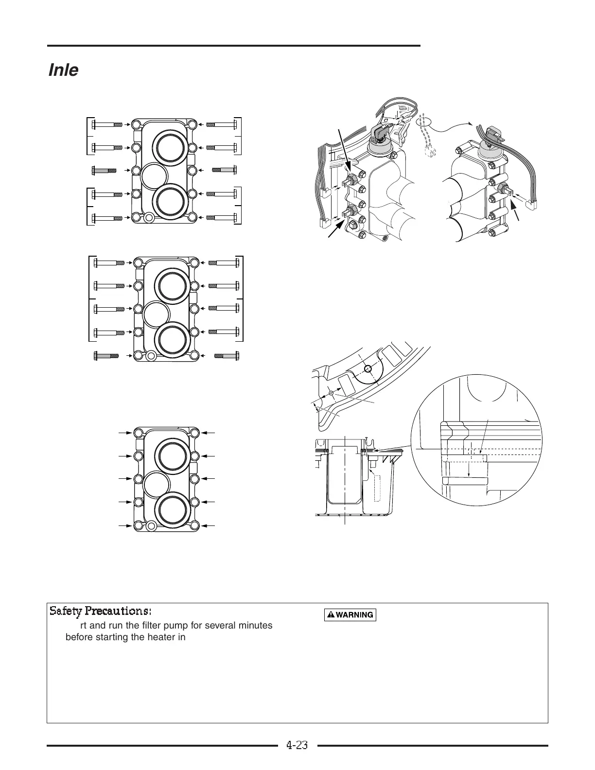
Inlet/Outlet Manifold
(Heaters built after 3/15/01)
SS
SS
aa
aa
ff
ff
ee
ee
tt
tt
yy
yy
PP
PP
rr
rr
ee
ee
cc
cc
aa
aa
uu
uu
tt
tt
ii
ii
oo
oo
nn
nn
ss
ss
::
::
• Start and run the filter pump for several minutes
before starting the heater in order to purge all air
from the system. Open all air vents in the system
(on Filter, Strainer, etc.) while purging the air. Run
the pump with the vents open until all vents run a
solid stream of water.
• Check gas union(s) for leaks with soapy water
before firing the heater.
Explosion and fire hazard. Be sure
that all gass connections are tight and do not
leak before attempting to start the heater.
• See Figure 4-5 for switch cover installation
instructions.
• Have a No. 77707-0008 Insulation Kit on hand in
case the heating coil shifts during manifold installa-
tion and requires opening the combustion chamber
cover to realign it.
Figure 4-3: Short bolt placement. Models
SR333/SRC333 use all long bolts.
Figure 4-4: Manifold Installation: Torque sequence.
You may have to retighten the bolts several times
to achieve the necessary torque.
Figure 4-5 Safety switch locations on the one-piece
manifold. When replacing a cast-iron adapter, move
the AGS from the opposite side. Be sure to route
wires around pressure switch as shown (to keep
them away from the combustion chamber top).