SECTION FOUR – Routine Maintenance and Professional Servicing
LL
LL
oo
oo
cc
cc
aa
aa
tt
tt
ii
ii
oo
oo
nn
nn
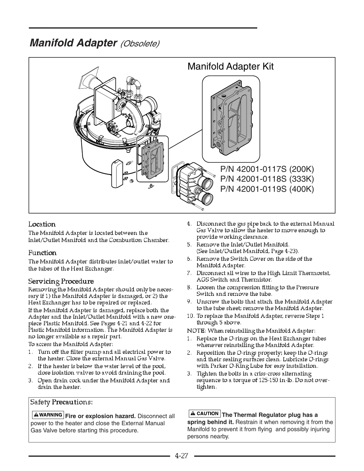
The Manifold Adapter is located between the
Inlet/Outlet Manifold and the Combustion Chamber.
FF
FF
uu
uu
nn
nn
cc
cc
tt
tt
ii
ii
oo
oo
nn
nn
The Manifold Adapter distributes inlet/outlet water to
the tubes of the Heat Exchanger.
SS
SS
ee
ee
rr
rr
vv
vv
ii
ii
cc
cc
ii
ii
nn
nn
gg
gg
PP
PP
rr
rr
oo
oo
cc
cc
ee
ee
dd
dd
uu
uu
rr
rr
ee
ee
Removing the Manifold Adapter should only be neces-
sary if 1) the Manifold Adapter is damaged, or 2) the
Heat Exchanger has to be repaired or replaced.
If the Manifold Adapter is damaged, replace both the
Adapter and the Inlet/Outlet Manifold with a new one-
piece Plastic Manifold. See Pages 4-21 and 4-22 for
Plastic Manifold information. The Manifold Adapter is
no longer available as a repair part.
To access the Manifold Adapter:
1. Turn off the filter pump and all electrical power to
the heater. Close the external Manual Gas Valve.
2. If the heater is below the water level of the pool,
close isolation valves to avoid draining the pool.
3. Open drain cock under the Manifold Adapter and
drain the heater.
4. Disconnect the gas pipe back to the external Manual
Gas Valve to allow the heater to move enough to
provide working clearance.
5. Remove the Inlet/Outlet Manifold.
(See Inlet/Outlet Manifold, Page 4-23).
6. Remove the Switch Cover on the side of the
Manifold Adapter.
7. Disconnect all wires to the High Limit Thermostat,
AGS Switch and Thermistor.
8. Loosen the compression fitting to the Pressur e
Switch and remove the tube.
9. Unscrew the bolts that attach the Manifold Adapter
to the tube sheet; remove the Manifold Adapter.
10. To replace the Manifold Adapter, reverse Steps 1
through 5 above.
NN
NN
OO
OO
TT
TT
EE
EE
::
::
When reinstalling the Manifold Adapter:
1. Replace the O-rings on the Heat Exchanger tubes
whenever reinstalling the Manifold Adapter.
2. Reposition the O-rings properly; keep the O-rings
and their sealing surfaces clean. Lubricate O-rings
with Parker O-Ring Lube for easy installation.
3. Tighten the bolts in a criss-cross alternating
sequence to a torque of 125-150 in-lb. Do not over-
tighten.
4-27