SECTION FOUR – Routine Maintenance and Professional Servicing
LL
LL
oo
oo
cc
cc
aa
aa
tt
tt
ii
ii
oo
oo
nn
nn
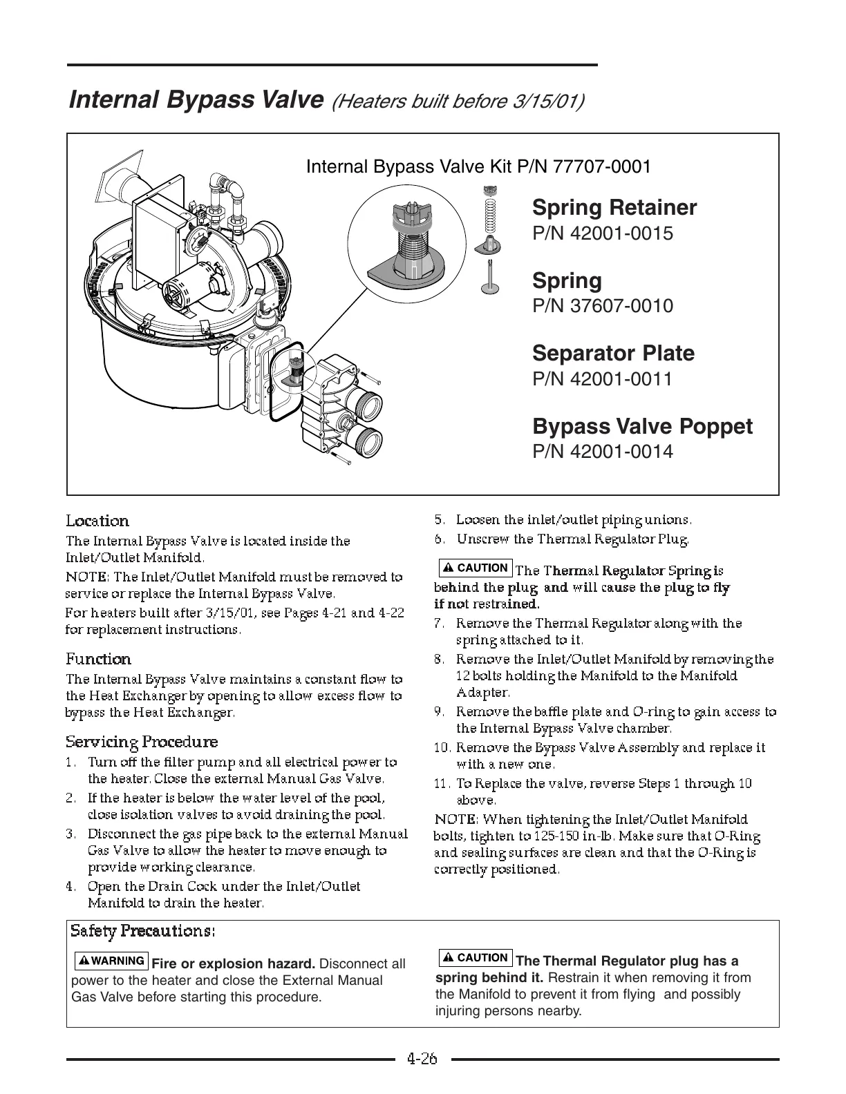
The Internal Bypass Valve is located inside the
Inlet/Outlet Manifold.
NN
NN
OO
OO
TT
TT
EE
EE
::
::
The Inlet/Outlet Manifold must be removed to
service or replace the Internal Bypass Valve.
For heaters built after 3/15/01, see Pages 4-21 and 4-22
for replacement instructions.
FF
FF
uu
uu
nn
nn
cc
cc
tt
tt
ii
ii
oo
oo
nn
nn
The Internal Bypass Valve maintains a constant flow to
the Heat Exchanger by opening to allow excess flow to
bypass the Heat Exchanger.
SS
SS
ee
ee
rr
rr
vv
vv
ii
ii
cc
cc
ii
ii
nn
nn
gg
gg
PP
PP
rr
rr
oo
oo
cc
cc
ee
ee
dd
dd
uu
uu
rr
rr
ee
ee
1. Turn off the filter pump and all electrical power to
the heater. Close the external Manual Gas Valve.
2. If the heater is below the water level of the pool,
close isolation valves to avoid draining the pool.
3. Disconnect the gas pipe back to the external Manual
Gas Valve to allow the heater to move enough to
provide working clearance.
4. Open the Drain Cock under the Inlet/Outlet
Manifold to drain the heater.
5. Loosen the inlet/outlet piping unions.
6. Unscrew the Thermal Regulator Plug.
TT
TT
hh
hh
ee
ee
TT
TT
hh
hh
ee
ee
rr
rr
mm
mm
aa
aa
ll
ll
RR
RR
ee
ee
gg
gg
uu
uu
ll
ll
aa
aa
tt
tt
oo
oo
rr
rr
SS
SS
pp
pp
rr
rr
ii
ii
nn
nn
gg
gg
ii
ii
ss
ss
bb
bb
ee
ee
hh
hh
ii
ii
nn
nn
dd
dd
tt
tt
hh
hh
ee
ee
pp
pp
ll
ll
uu
uu
gg
gg
aa
aa
nn
nn
dd
dd
ww
ww
ii
ii
ll
ll
ll
ll
cc
cc
aa
aa
uu
uu
ss
ss
ee
ee
tt
tt
hh
hh
ee
ee
pp
pp
ll
ll
uu
uu
gg
gg
tt
tt
oo
oo
ff
ff
ll
ll
yy
yy
ii
ii
ff
ff
nn
nn
oo
oo
tt
tt
rr
rr
ee
ee
ss
ss
tt
tt
rr
rr
aa
aa
ii
ii
nn
nn
ee
ee
dd
dd
..
..
7. Remove the Thermal Regulator along with the
spring attached to it.
8. Remove the Inlet/Outlet Manifold by removing the
12 bolts holding the Manifold to the Manifold
Adapter.
9. Remove the baffle plate and O-ring to gain access to
the Internal Bypass Valve chamber.
10. Remove the Bypass Valve Assembly and replace it
with a new one.
11. To Replace the valve, reverse Steps 1 through 10
above.
NN
NN
OO
OO
TT
TT
EE
EE
::
::
When tightening the Inlet/Outlet Manifold
bolts, tighten to 125-150 in-lb. Make sure that O-Ring
and sealing surfaces are clean and that the O-Ring is
correctly positioned.
4-26
Internal Bypass Valve
(Heaters built before 3/15/01)
SS
SS
aa
aa
ff
ff
ee
ee
tt
tt
yy
yy
PP
PP
rr
rr
ee
ee
cc
cc
aa
aa
uu
uu
tt
tt
ii
ii
oo
oo
nn
nn
ss
ss
::
::
Fire or explosion hazard. Disconnect all
power to the heater and close the External Manual
Gas Valve before starting this procedure.
The Thermal Regulator plug has a
spring behind it. Restrain it when removing it from
the Manifold to prevent it from flying and possibly
injuring persons nearby.
Spring Retainer
P/N 42001-0015
Spring
P/N 37607-0010
Separator Plate
P/N 42001-0011
Bypass Valve Poppet
P/N 42001-0014