S6
INSTRUCTIONS
DIGITAL SPEEDOMETER MK2, UNIVERSAL
EN
14
1. Introduction
Thank you for purchasing the STAGE6 DIGITAL SPEEDO-
METER MK2. Before installing and operating the instrument,
please read the instructions carefully and retain them
for future reference.
1. The instrument requires a 12V DC supply.
2. To install the instrument, please follow the steps as de-
scribed in the manual. For any damage caused by incorrect
installation, the user shall be held responsible.
3. To avoid short-circuits, please don’t pull the wires during
installation. Don’t break or modify the wire terminals.
4. Do not disassemble or change any parts other than the
ones referred to in this manual.
5. All interior examination or maintenance should be carried
out by our professionals.
Explanation of Symbols
Information after this symbol will help you understand es-
sential steps.
Follow these instructions accurately to avoid damage.
Some instructions must be followed to avoid damage to
yourself or others.
Some instructions must be followed to avoid damage to the
vehicle.
WARNING
CAUTION
NOTE
NOTE
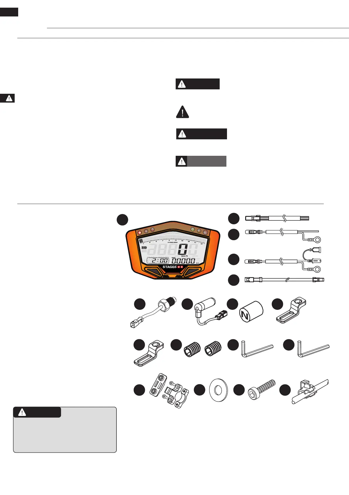
1.1 Accessories
1 Instrument (1 pc.)
2 Power cable (1 pc.)
3 RPM cable (type A) (1 pc.)
4 RPM cable (type B) (1 pc.)
5 Temperature sensor cable (1 pcs.)
6 Water temperature sensor PT 1/8 (1 pcs.)
7 Digital speed sensor (1 pc.)
8 Magnet D6 x 5L mm (6 pcs.)
9 Speed sensor bracket, type S, M8 (1 pc.)
10 Speed sensor bracket, type S, M10 (1 pc.)
11 Grub screw M5 x 5L (2 pcs.)
12 Hex key 2.5mm (1 pc.)
13 Hex key 4mm (1 pc.)
14 Instrument bracket (1 pc.)
15 Washer M5 (2 pcs.)
16 Screw M5 x 15L (2 pcs.)
17 Connecting clip (2 pcs.)
Please contact your local distributor if
the items you have received are diffe-
rent from the ones listed above!
2
4
3
5
6
10
1211 13
14
17
15 16
7
1
8 9
DIGITAL
 Loading...