15
NOTE
If you don’t install and connect the temperature
sensor, the temperature will not be displayed.
When connecting the power cable, please
make sure to follow the instructions. If you
connect the red wire and the brown wire in
parallel, the meter will not work properly.
NOTE
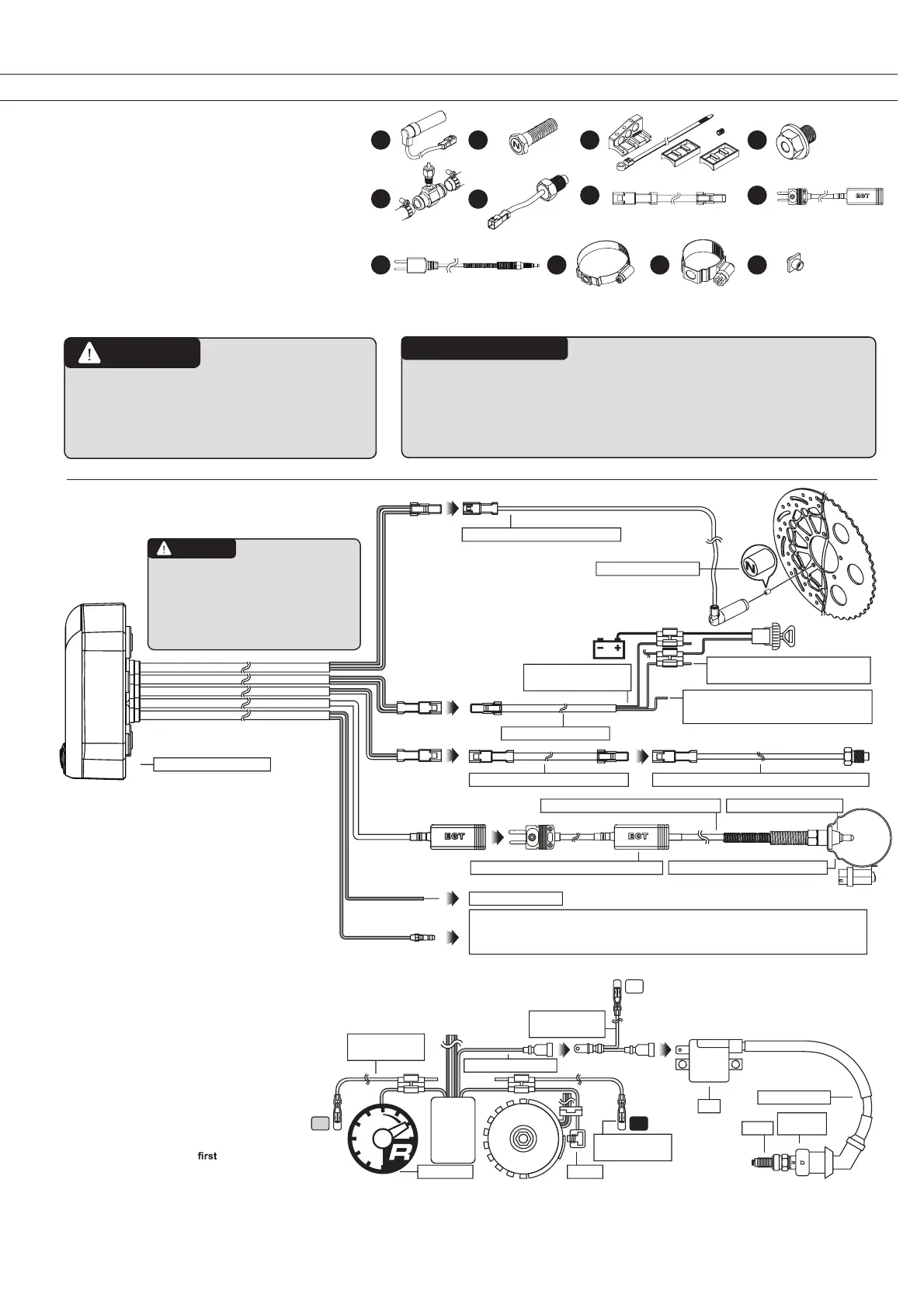
2. Wiring Diagram
1.2 Optional Accessories
2 3 41
1 Active speed sensor
2 Magnetic screw for brake disc
3 Speed sensor bracket, type L
4 Oil temperature sensor adapter
5 Water temperature sensor adapter
6 Temperature sensor
7 Temperature sensor cable (2 m)
8 Temperature extension wire
9 EGT temperature sensor
10 Stainless clamp(40~64mm)
11 Stainless clamp(21~38mm)
12 M5 bolt
These parts are not included in the delivery
but can be purchased separately. For further
information, please contact your local distribu-
tor.
This type of RPM wire is intended only for fuel injection models. Before installation, please make sure
that the signal voltage peak of the coil range is between 15–24V. If the signal voltage is below 15V, the
instrument may not be able to read the RPM signal. Attention: Voltages higher than 24 V may damage
the instrument!
Brown / positive terminal
connect to 12V DC ignition switch
Green / ground wire
connect to frame or engine (important: good
ground)
Installation of the RPM Wire
A: Please connect the RPM wire (type B) to the
positive terminal of the ignition coil.
B: Please connect the RPM wire (type A) to the
pick-up.
C: Please connect the RPM wire (type A) and the
original tachometer signal wire in parallel. This
method is available only if the original speedo-
meter features a tachometer readout. You can get
the RPM wire information from the service manual
of your scooter.
For multi-ignition models, we recommend
picking up the signal at the
ignition. The
best signal source is C>B>A. If you have
problems picking up a clear RPM signal, we
recommend trying out different installation
options.
Spark plug cable
Pick-upTachometer
EMS
CDI
Flywheel
Ignition coil (positive)
RPM cable type A
(accessory 3)
RPM cable type B
(accessory 4)
Ignition
pulse
Spark
Coil
Spark plug
cap
RPM cable type A
(accessory 3)
Temperature sensor cable (accessory 5)
Temperature extension wire (Option accessory 8)
Stainless clamp(Option accessory 10/11)
EGT temperature sensor (Option accessory 9)
Black / fuel (negative)
Water temperature sensor TH-01 PT1/8 (accessory 6)
Red / positive terminal
connect to 12 V DC battery
Power cable (accessory 2)
Digital speed sensor (accessory 7)
Magnet (accessory 8)
Instrument (accessory 1)
5
9
10 1211
6
7 8
Active Speed Sensor
The advantages of the active speed sensor are as follows: 1. You don’t need to
install the magnet opposite the speed sensor. 2. You can set up the sensor signal
input with up to 60 points, which will result in a more accurate speed display.
Please note that the speed sensor included in the kit is a passive speed sensor,
which can pick up 20 sensor points at the most.
M5 bolt (Option accessory 12)
A
B
C
 Loading...