S6
INSTRUCTIONS
DIGITAL SPEEDOMETER MK2, UNIVERSAL
EN
18
NOTE
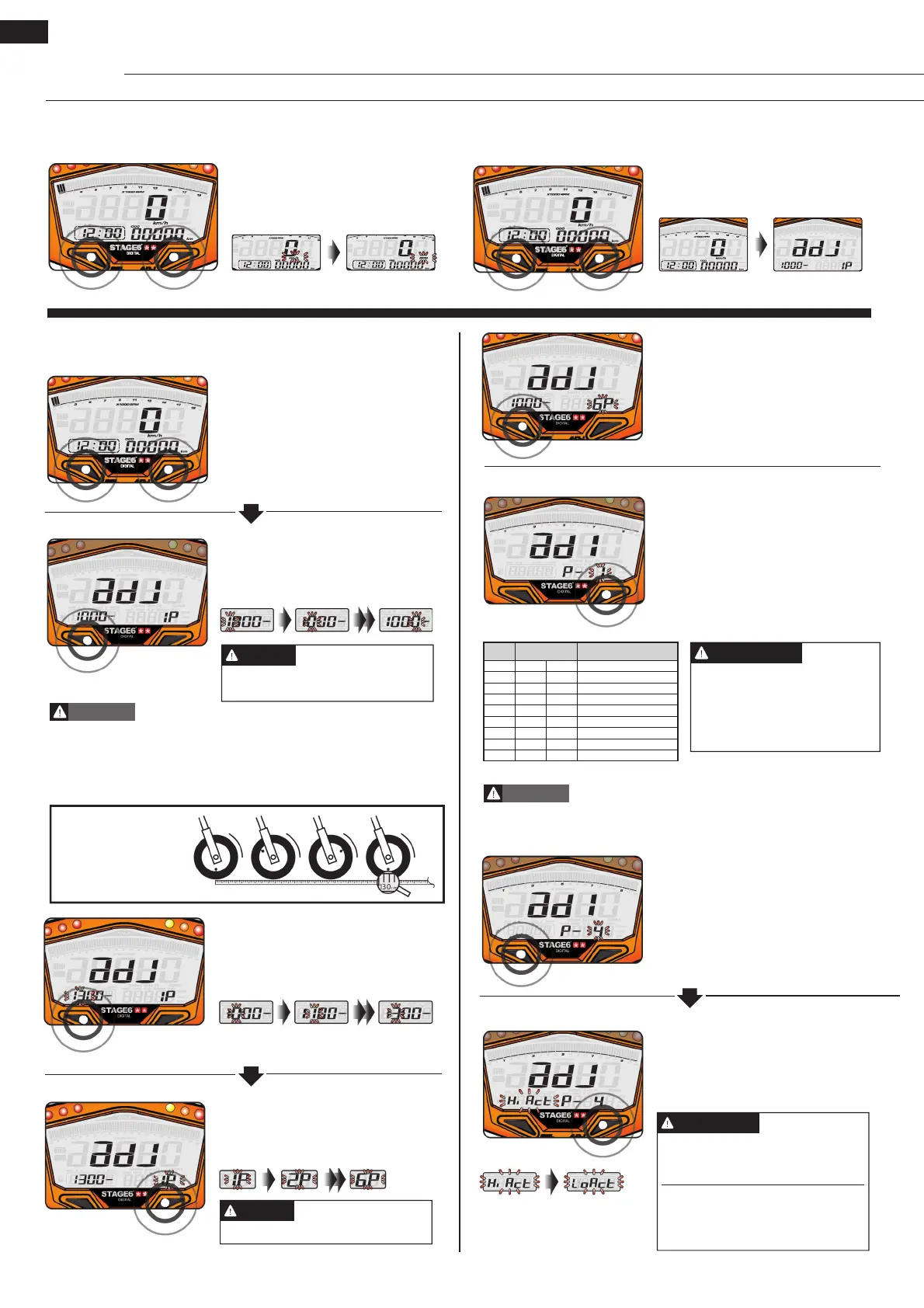
4.1.3 Pressing Both Buttons At Once (In Main Screen)
• Press both buttons at once to switch
from digital speedometer to digital
tachometer.
• In the main screen, press and
hold both buttons for 3 seconds to
enter the tyre circumference and the
number of sensor points.
• Press the Adjust Button to change
the respective digit.
• E.g.: The tyre circumference setting
has been changed from 1,000 mm to
1,300 mm.
• Press the Adjust Button to enter the
respective number.
• E.g.: The number of sensor points
is 6.
• E.g.: The tyre circumference is
1,300 mm.
• Press the Select Button to move
between digits.
• Press and hold both buttons for
3 seconds to enter set-up mode (see
4.2).
4.2 Setting Up the Instrument
Setting range: 300–2,500 mm
Setting unit: 1 mm
NOTE
In Main Screen
Tyre Circumference
• Please measure the circumference of the tyre you will install the sensor on
and check the number of magnet sensor points (magnets can be installed
e.g. in disc screws.)
• The speed displayed on the instrument will be affected by this setting, so
please make sure to enter the correct value.
WARNING
Four-stroke engines with one cylinder that ignite every 360° will have to be
treated just like two-stroke engines with one cylinder.
CAUTION
When measuring the
tyre circumference with a
measuring tape, you can
use the valve as starting
and end point.
• E.g.: The number of sensor points
has been changed from 1 to 6.
• Press the Select Button to get to the
setting of the RPM pulse.
• E.g.: The value has been changed to
2 (4C 4P).
• Press the Select Button to get to the
setting of the negative impulse.
Setting range: max. 20
NOTE
The following settings are pos-
sible:
0.5, 1, 1.5, 2, 2.5, 3, 4, 5, 6
C stands for number of cy-
cles, P for number of pistons.
• E.g.: The current value is to be
changed to 2.
• Press the Adjust Button to enter the
respective value. To see which value
is the correct one, see table below.
• E.g.: The value is 0.5 (4C-1P).
RPM Pulse
• E.g.: The setting is to be changed to
“Lo” (negative impulse).
• Press the Adjust Button to change
the input signal.
Negative Impulse
• Press the select button to enter the
number of sensor points.
Setting
value
Cycle and piston
number
Number of RPM signals per
ignition
0.5 4C-1P 2 signals per ignition
1 2C-1P 4C-2P 1 signal per ignition
1.5 4C-3P 2 signals per 3 ignitions
2 2C-2P 4C-4P 1 signal per 2 ignitions
2.5 4C-5P 2 signals per 5 ignitions
3 2C-3P 4C-6P 1 signal per 3 ignitions
4 2C-4P 4C-8P 1 signal per 4 ignitions
5 4C-10P 1 signal per 5 ignitions
6 2C-6P 4C-12P 1 signal per 6 ignitions
Sensor Points
You can set the impulse to “Hi” (po-
sitive impulse) or to “Lo” (negative
impulse).
If the tachometer can’t get a signal
(no RPM displayed on the screen),
try out the other setting.
NOTE
 Loading...