9
EN
COM
STA
PHO
1
PHO
1+2
STOP
PED
+24V-
M1
S1
+ 5V -
S2
M2
24VAC
COMFCO FCC
ANT
E
0000
FUSE
L N
5
9
8 7 6
10
11
12
13
14 15
16
17
18
4
1
3
2
INSTALLATION AND PROGRAMMING INSTRUCTIONS
This manual is intended for qualied technical personnel responsible for installations.
Please read these instructions carefully prior to installation.
Improper use of the product or a connection error could affect proper operation and end user safety.
Supply power: 230V ~ ±10% - 50Hz
On-board 433MHz receiver: 76 transmitters MAX
Operating temperature: -20°C / +60°C
Electronic anti-crushing device: amperometric + encoder
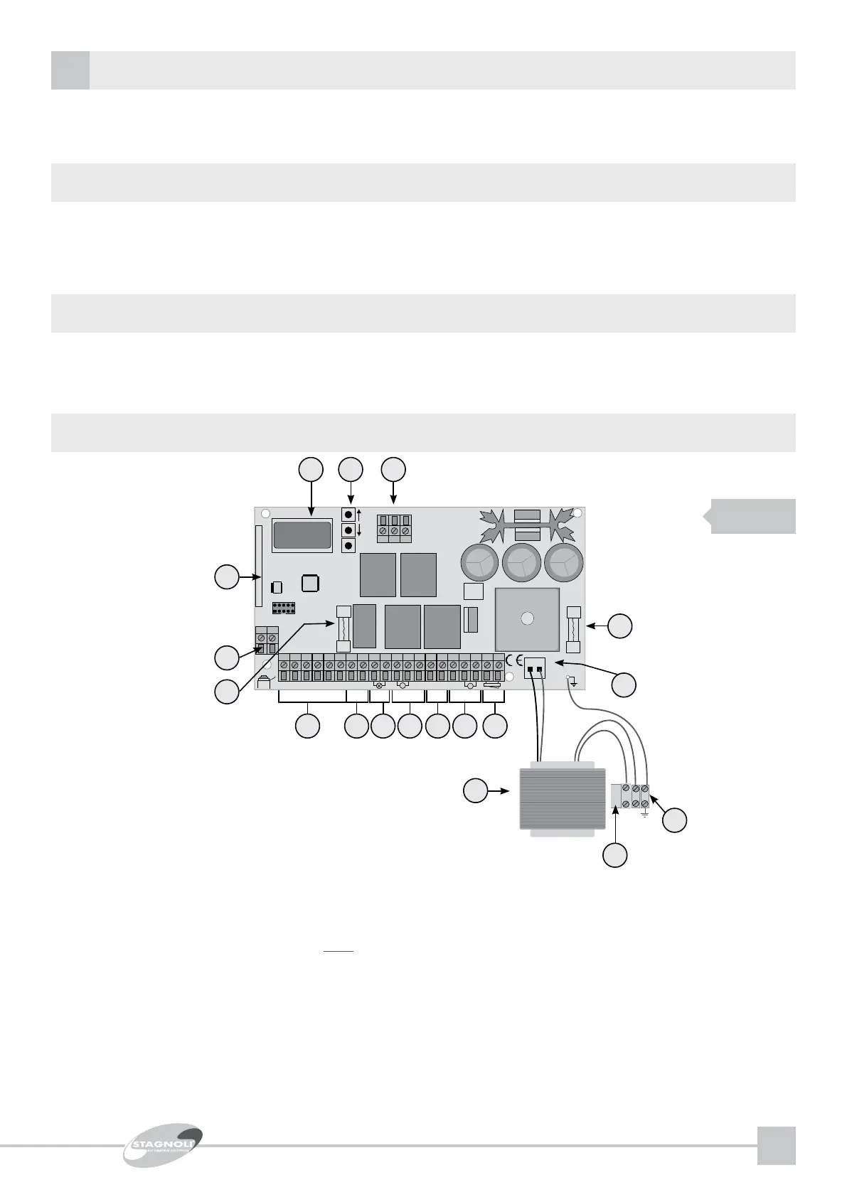
DESCRIPTION OF PARTS
1- Line fuse 230V (T2.5A 5x20)
2- Terminal board for transformer line connection
3- Primary transformer 230V, secondary 24V~, 130VA
4- Molex power 24 V~, and hole for auxiliary grounding (to be welded)
5- Supply power fuse, (F10A 5x20)
6- Terminal board for mechanical/magnetic limit stop (ONLY for pre-set models)
7- Menu navigation buttons
8- 4-language LCD display (IT,EN,FR,ES)
9- Receiver model 433Mhz Rollingcode/xed code
10- Terminal for external antenna
11- Auxiliary power fuse 24Vac, (F2A 5x20)
12- Terminal board for control and safety connection
13- Auxiliary power 24V~, (24Vdc with battery supply power)
14- Steady light ashing light power, 24V~ (24Vdc with battery supply power)
15- Motor 1 connection
16- Encoder supply power 5Vdc
17- Motor 2 connection
18- Electric lock 12Vdc 10W (max 2 sec)
FIG 1
TECHNICAL DATA
MAX ashing light output power: 24V~ - 25W
MAX electric lock output power: 12Vdc - 10W (max 2 Sec)
Accessory supply power 24V~ - 25W
Maximum motor power current: 3.5A+3.5A
The “H24” 24V version control unit is for use on automatic residential and condominium sliding gates for intensive use. Any use differing from
that described herein or installations performed differently from that set forth in the following technical manual are prohibited.
INTENDED USE AND LIMITATIONS OF USE