Do you have a question about the Standard Horizon GX1250SA and is the answer not in the manual?
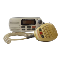
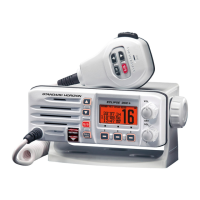
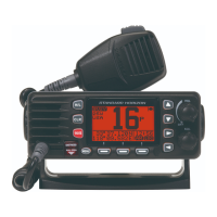
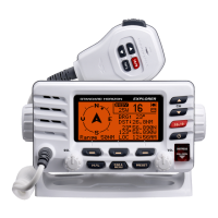
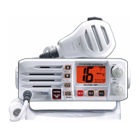
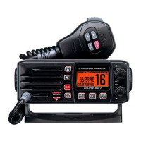
Overview of the GX1250SA VHF/FM marine transceiver and its key features.
Regulatory details for FCC and Industry Canada license applications.
Contents of the GX1250SA transceiver package upon unboxing.
List of available optional accessories for the GX1250SA.
Explanation of the PLL circuit's function in frequency control.
Detailed breakdown of the super-heterodyne receiver architecture.
Explanation of the transmitter's operational flow and components.
Block diagram and description of the transceiver's power supply.
Microprocessor QL01 port functions and control signal operations.
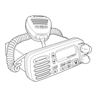
Step-by-step guide to detach the front case and chassis block.
Instructions for safely removing the control Printed Circuit Board.
Procedure for removing the transmitter/receiver Printed Circuit Board.
Visual guide to test points and adjustment components.
How to enter the transceiver's diagnostic and adjustment mode.
Method for initiating test mode via pin short-circuiting.
Adjusting and confirming the VCO lock voltage for stability.
Setting and verifying high and low RF power output levels.
Calibrating transmission and local reception frequencies.
Adjusting and confirming the audio modulation level.
Procedure for setting the receiver's local level.
Tuning front-end components for optimal reception.
Fine-tuning the intermediate frequency (IF) coils.
Verifying receiver performance using SINAD measurements.
Calibrating and confirming weather alert tone detection.
Testing all segments of the Liquid Crystal Display.
Reviewing the transceiver's factory default configurations.
Reference table for channel frequencies across regions.
Overall performance and physical characteristics of the transceiver.
Detailed technical parameters for the transmitter.
Detailed technical parameters for the receiver.
| Type | Fixed Mount VHF Marine Transceiver |
|---|---|
| Power Output | 25W / 1W |
| Waterproof Rating | IPX7 |
| Weight | 2.2 lbs |
| NOAA Weather Channels | Yes |
| DSC Capability | Yes |
| Display | LCD |
| Channels | All USA, International, and Canadian channels |
| Speaker | Built-in |