Do you have a question about the Standard Horizon Intrepid LE GX1265S and is the answer not in the manual?
| Type | Marine VHF Transceiver |
|---|---|
| NOAA Weather Channels | Yes |
| Speaker Output | 4.5W |
| DSC Capability | Yes |
| GPS Interface | NMEA 0183 |
| Power Output | 25W / 1W |
| Display | LCD |
| Frequency Range | 156.025 - 163.275 MHz |
| Channels | All USA, International & Canadian Channels |
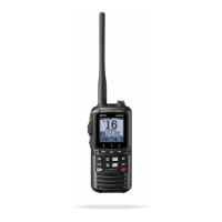
Introduces the INTREPID LE transceiver and its features, encouraging thorough manual review.
Provides data for license applications and references a supplementary document for detailed FCC/Industry Canada information.
Lists the contents included in the transceiver package upon initial opening.
Details optional accessories available for the transceiver, including brackets and speakers.
Defines transceiver controls and connections, referencing Figure 1 for location details.
Provides guidelines for selecting an optimal mounting location for the radio unit.
Details correct connection procedures for the power cord and antenna to the transceiver.
Explains accessory cable pinout and connection for GPS receivers and external speakers.
Provides step-by-step instructions for installing the transceiver using the CMB16 flush mount bracket.
Guides users through receiving transmissions, including setting volume and squelch.
Explains transmission steps, including channel monitoring and PTT switch usage.
Describes the Transmit Time-Out Timer (TOT) feature for limiting transmission duration.
Refers to supplementary material for simplex and duplex channel usage instructions.
Explains how to change and select between USA, Canadian, and International operating modes.
Details how to access and switch between NOAA weather channels.
Describes how to enable and receive NOAA weather alerts, including the alert tone.
Explains programming channels into memory and initiating memory scanning.
Details activation and usage of Channel 16 Priority Scanning (PRI-SCAN).
Describes displaying vessel position (LAT/LON) when connected to a GPS receiver.
Provides instructions for resetting the transceiver to its factory default conditions.
Provides an overview of Digital Selective Calling (DSC) and its designation by IMO and GMDSS.
Explains DSC as a semi-automated method for establishing radio calls, including distress, urgency, and safety.
Defines MMSI as a nine-digit number for selective calling and explains how to obtain an assignment.
Guides users through sending a distress call, including automatic position transmission.
Explains initiating an individual DSC call to a specific party for voice communication.
Details establishing contact with other vessel stations using the All Ships Call function.
Describes the DSC Standby function for replying to unattended DSC calls and logging them.
Explains the Call Waiting directory that logs received distress and individual calls.
Details accessing and reviewing distress calls logged in the Call Waiting directory.
Details accessing and reviewing individual calls logged in the Call Waiting directory.
Outlines receiving various DSC transmissions, including distress and individual calls.
Describes procedure and alerts upon receiving a distress call.
Explains reception of a distress relay call and associated alarms.
Details reception of an all ships call and required monitoring actions.
Explains reception of a geographical area call and required monitoring actions.
Describes reception of an individual call and the need to send an acknowledgment.
Introduces the main SETUP menu for configuring transceiver settings.
Guides users on adjusting the brightness level of the transceiver's backlight.
Explains adjusting the contrast level of the LCD display for improved readability.
Details setting up individual contact entries in the DSC directory.
Describes enabling or disabling the audible beep for key presses.
Explains setting the time difference between local time and UTC.
Guides users through inputting their unique MMSI number into the transceiver.
Explains enabling or disabling the DSC scan feature.
Lists commonly requested replacement parts and their associated part numbers.
Provides a chart to diagnose and resolve common transceiver problems and their remedies.
Lists general specifications including channels, input voltage, current drain, and dimensions.
Details transmitter technical specifications, including frequency range and RF output.
Provides receiver technical specifications, including sensitivity and selectivity.