L54 – Manual
WAM454A 8 Standby AB – standbygroup.se
Connections
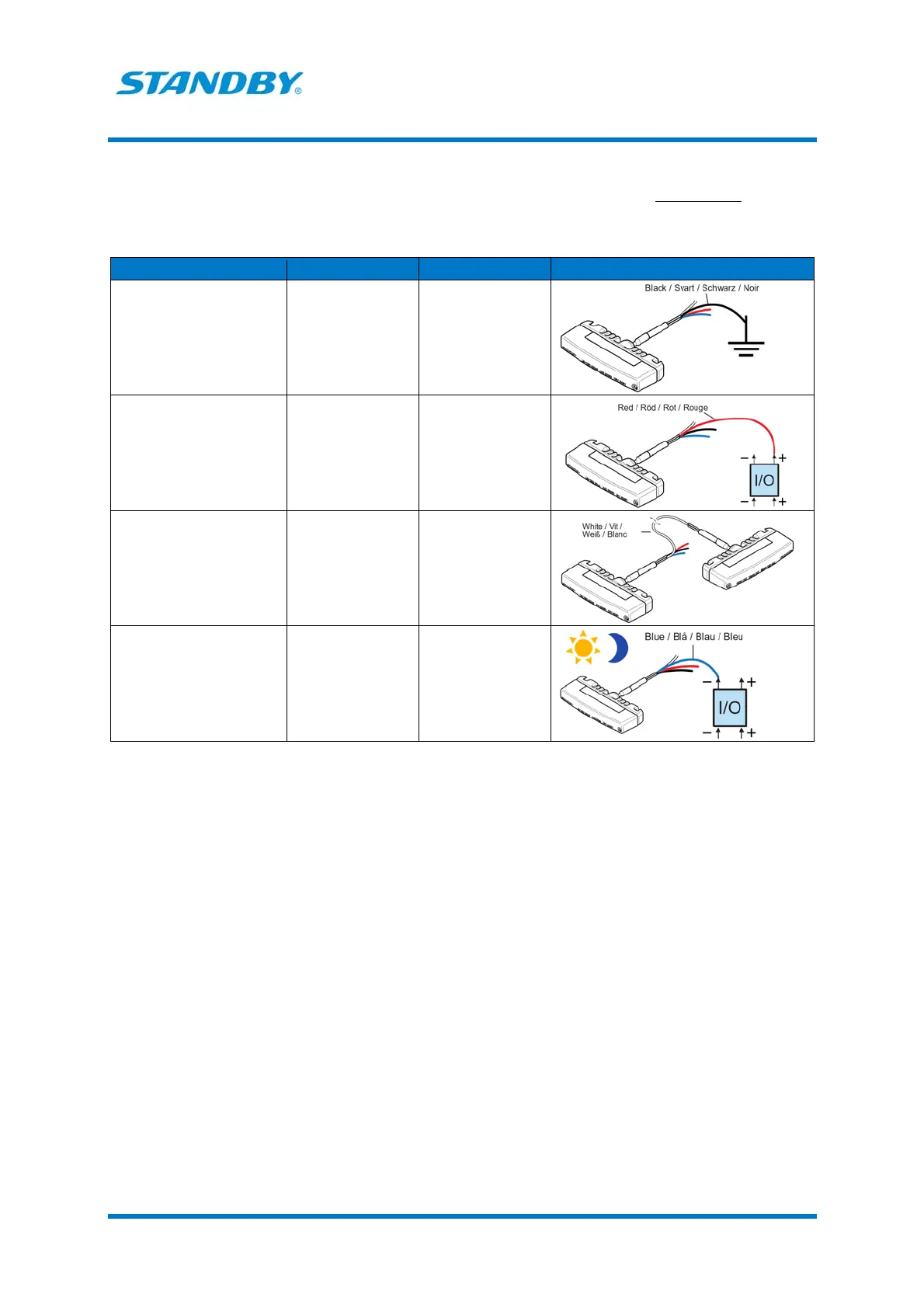
The function of each wire and how to connect the wires depend on the chosen flash pattern setting.
Table 1. Connections when flash pattern Double/Double, Double/Triple, Double/Steady
burn or Triple/Steady burn is selected.
Wire Functions Connect to
Black Power supply Good and suitable
ground
Red Power supply
Lamp on/off
10-30 V DC via a 5 A
fuse
Sourcing output (+)
of an I/O unit or via
a switch
White Synchronizing the
flashing of two or
more lamps
Sync cable of the
other lamp
Blue Day-and-night
function
Sinking output (-) of
an I/O unit or via a
switch to ground.
When activated, the
lamp dims down to
night level.
 Loading...