8
LOCATION
When choosing a location for this appliance you
must have:
(a) Sufficient room for the installation (see
clearances), a satisfactory flue (see flue
system), and an adequate air supply for correct
combustion and operation (see Ventilation and
Combustion air supply).
(b) Adequate space for maintenance and air
circulation.
(c) Solid floor or base of non-combustible material
which is capable of supporting the total weight.
(see Technical Data).
Note: Installation should be carried out in a well
ventilated area.
HEARTH CONSTRUCTION
When a non-combustible floor surface is not
available,
then the cooker must be placed on other
insulating material. We recommend a slab of
precast concrete 40mm (1
1
/2) inches deep. If other
insulating material is being used, the dimensions of
the slab of this insulating material must afford similar
protection. This hearth must extend 150mm (6
inches) to either side of the appliances and 225mm
(9 inches) to the front.
ELECTRICAL SUPPLY
All wiring external to the appliance must conform to
the current BS 7671 (U.K.), & Safety Document 635,
ETC: Part 1 Section 5.6.4. The Electricity at Work
Regulations. The cooker requires a 230V–240V, 50
Hz supply. Connection of the appliance and any
system controls to the mains supply must be
through a moulded on plug top, (which is fitted with
a 3 amp fuse) which is fitted to the appliance in
accordance with EN 60335, Consumer Protection,
SI 1994 No. 1768, plug and sockets etc. (safety)
Regulations 1994.
Always install in accordance with current local wiring
regulations.
You should always, when either exposing or working
with wiring, consult a qualified electrician.
WARNING: THIS SUPPLY MUST BE EARTHED
(Refer to B.S. 7430: Code for Practice of Earthing).
Where a risk of low voltage can occur, a voltage
sensitive device should be fitted to prevent start up
of the burner so as not to endanger the installation.
The primary fuse is located in the control box tray.
To isolate the appliance completely unplug from the
mains socket. Always ensure that this socket is
easily accessible and close to the appliance.
Persons in charge of this appliance should be aware
of this socket outlet position.
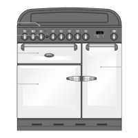
TO ACCESS THE CONTROL PANEL (See Fig.3)
a. The plinth can be removed by sliding it
approximately 20mm to the left.
b. Remove the 6 screws which hold the kicker
panel in place.
c. Remove the 2 retaining screws on either
side of the Control Consul.
d. Carefully withdraw the Control Consul, ensuring
that no strains are subjected to the wiring.
e. Connection to be carried out in accordance with
the Wiring Diagrams. (See fig’s 26 to 29
Inclusive)
Fig. 3
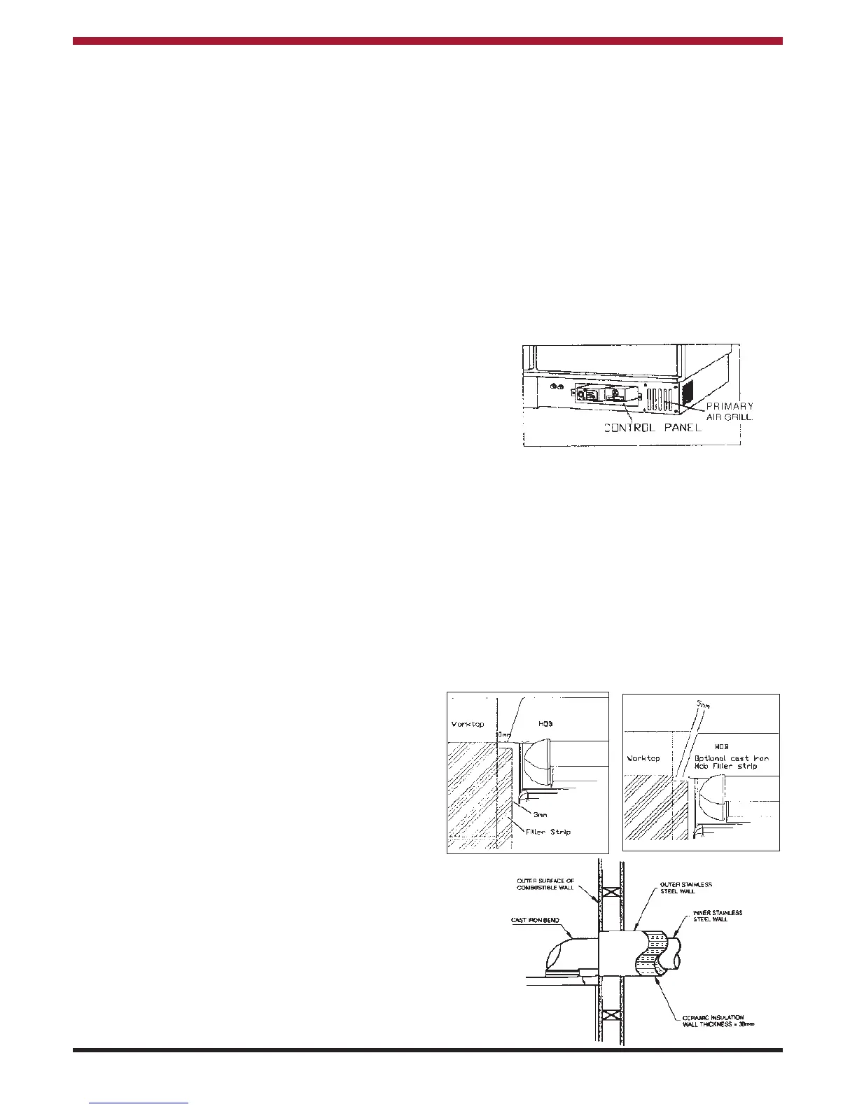
CLEARANCES TO COMBUSTIBLES
When bringing your kitchen units up to the sides of
the cooker leave a 10mm gap between the Stanley
and adjacent units, this gap can be reduced by
fitting an optional hob side filler strip to the Stanley
leaving a 5mm gap (see fig. 4 & 5). Likewise the
base of your units can be brought up flush to the
Stanley’s built-in plinth.
When bringing the work top up to the side of the hob
leave a 10mm gap to combustible material (see fig.
4).
Fig 4
Fig 5
Fig. 6
 Loading...