7
PLUMBING
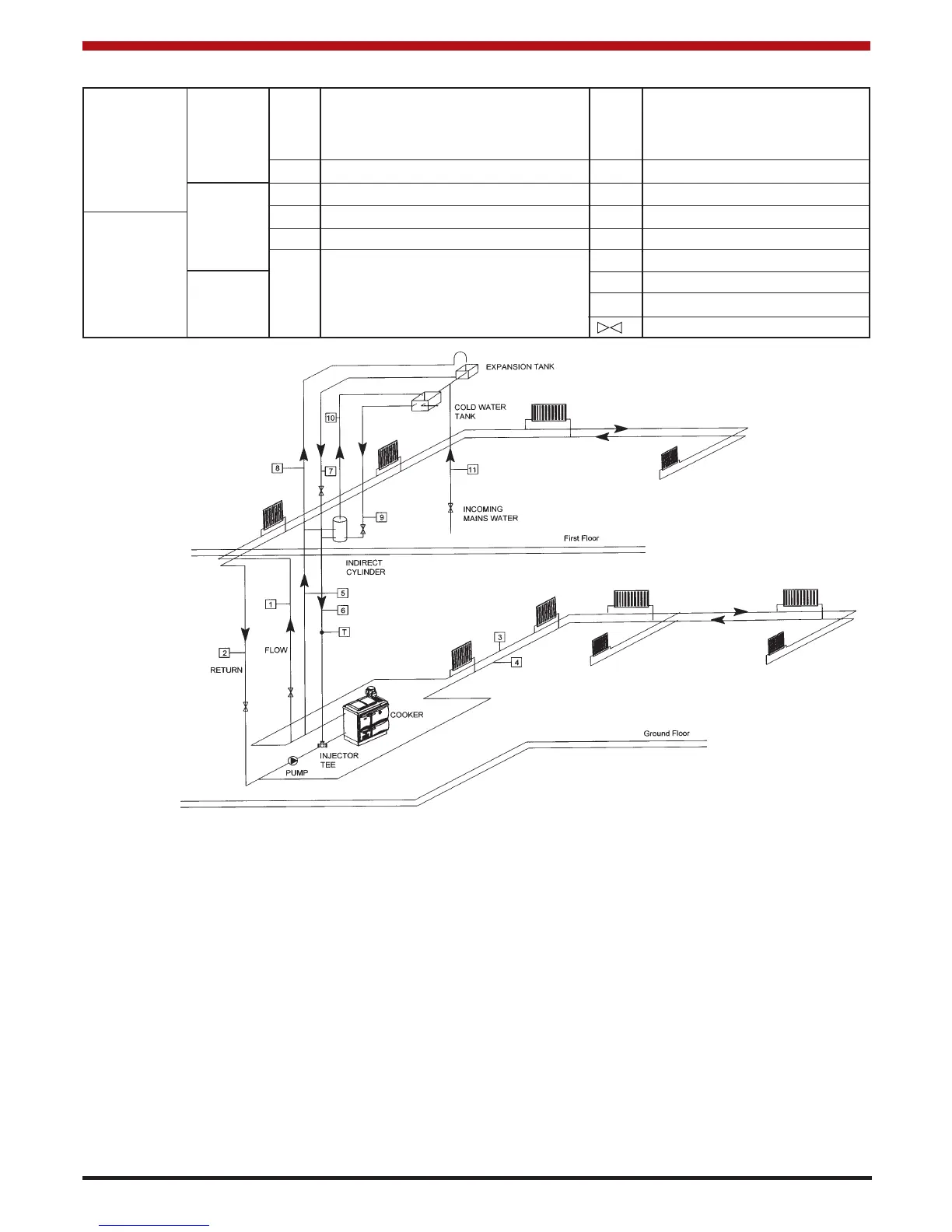
PIPE FUNCTION PIPE FUNCTION
RADIATOR FIRST
HEATING FLOOR 1 PUMPED FLOW TO RADIATORS 7 HOT WATER FLOW
CIRCUITS 2 PUMPED RETURN EX 8 COLD WATER (EX TANK)
3 PUMPED FLOW TO RADIATORS 9 COLD FEED-HEAT SYSTEM
GROUND 4 PUMPED RETURN EX 10 OPEN VENT-HEAT SYSTEM
CYLINDER FLOOR 5 GRAVITY FLOW TO CYLINDER 11 COLD FEED TO CYLINDER
HEATING 6 GRAVITY RETURN EX 12 HOT WATER VENT
CIRCUIT FIRST 13 MAINS WATER
FLOOR T THERMOSTAT
ISOLATING VALVES
This diagram
illustrates the basic
principals of water
systems and is not to
be regarded as a
working drawing.
Recommended indirect cylinder 135-180 litres, depending on domestic requirements with a 2.5 cm (1”) flow and return
pipes not exceeding 7.8m (25’6”) each in length. Cylinder and pipework should be lagged to minimise heat losses.
REGULATIONS
The plumbing must be in accordance with all
relevant regulations and practices. It must include a
gravity circuit with expansion pipe, open to the
atmosphere. The central heating will normally be
pump-driven as with other types of boilers. In
indirect domestic water closed circuit central heating
the system is thermostatically controlled by the unit
mounted in the ashpit door.
BOILER OUTPUT
High output cannot be maintained unless fuel is
being burned at a rate of 4.6 Kg. per hour of coal.
When burning peat or wood, reduced output will
apply because of the lower calorific value of the
fuels.
GRAVITY CIRCUIT
The gravity circuit consists of the domestic hot water
tank of 135 - 180 litres indirect cylinder, fixed in an
upright position, recommended for hot water storage
and it should be connected to the boiler by 25mm
(1”) ID flow and return piping. The pipes should not
exceed 7.8m (25’6”) each in length and anything in
excess of 4.6m (15ft.) must be fully lagged. The
shorter the run of pipe work the more effective the
water heating efficiency and to this end, the cylinder
should be fully lagged. For safety’s sake do not
have any valves on this circuit.
Fig. 5