14
ENGLISH
Keep bystandersaway.
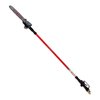
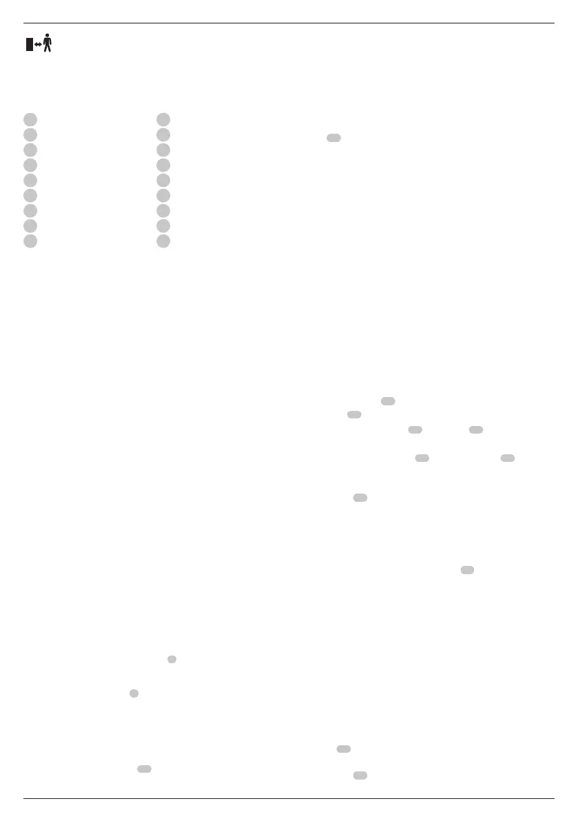
Description (Fig. A)
WARNING: Never modify the power tool or any part of it.
Damage or personal injury couldresult.
1
Handle assembly
2
Center extension pole
3
Saw head assembly
4
Trigger switch
5
Lock button
6
Battery
7
Foam gripper
8
Threaded pole
9
Threaded sleeve
10
Bar clamp
11
Sprocket cover
12
Hex head screws
13
Guide bar
14
Saw chain
15
Scabbard
16
Hex wrench
17
Oil bottle
18
Branch removal hook
Intended Use
This pole saw is ideal for pruning applications and cutting limbs
up to 203 mm indiameter.
DO NOT use under wet conditions or in the presence of
flammable liquids orgases.
This pole saw is a professional powertool.
DO NOT let children come into contact with the tool.
Supervision is required when inexperienced operators use
thistool.
• Young children and the infirm. This appliance is not
intended for use by young children or infirm persons
withoutsupervision.
• This product is not intended for use by persons (including
children) suffering from diminished physical, sensory or
mental abilities; lack of experience, knowledge or skills
unless they are supervised by a person responsible for their
safety. Children should never be left alone with thisproduct.
ASSEMBLY AND ADJUSTMENTS
WARNING: To reduce the risk of serious personal
injury, turn tool off and disconnect battery pack
before making any adjustments or removing/
installing attachments or accessories. An accidental
start-up can causeinjury.
WARNING:Use only battery packs andchargers.
Inserting and Removing the Battery Pack
from the Tool (Fig. B)
NOTE: Make sure your battery pack
6
is fullycharged.
To Install the Battery Pack into the Tool Handle
1. Align the battery pack
6
with the rails inside the tool’s
handle (Fig. B).
2. Slide it into the handle until the battery pack is firmly seated
in the tool and ensure that you hear the lock snap intoplace.
To Remove the Battery Pack from the Tool
1. Press the release button
24
and firmly pull the battery pack
out of the toolhandle.
2. Insert battery pack into the charger as described in the
charger section of thismanual.
Fuel Gauge Battery Packs (Fig. B)
Some battery packs include a fuel gauge which consists
of three green LED lights that indicate the level of charge
remaining in the batterypack.
To actuate the fuel gauge, press and hold the fuel gauge
button
27
. A combination of the three green LED lights will
illuminate designating the level of charge left. When the level
of charge in the battery is below the usable limit, the fuel gauge
will not illuminate and the battery will need to berecharged.
NOTE: The fuel gauge is only an indication of the charge left on
the battery pack. It does not indicate tool functionality and is
subject to variation based on product components, temperature
and end‑userapplication.
Installing and Removing Saw Chain
(Fig. A, C–E)
WARNING: Sharp moving blade. To prevent accidental
operation, insure that battery is disconnected from the
handle before performing the following operations. Failure
to do this could result in serious personal injury.
CAUTION: Sharp moving blade. Always wear protective
gloves when installing or removing the chain. The chain is
sharp and can cut you when it is notrunning.
1. Place the pole saw on a firm surface. Rotate the two
hex head screws
12
counterclockwise with the hex
wrench
16
provided.
2. Remove sprocket cover
11
, bar clamp
10
, and hex
headscrews.
3. To remove the saw chain
14
, rotate the screw
19
in the
front of the housing using the flat screwdriver end of the
wrench. Turning the screw counterclockwise allows the
guide bar
13
to recede and reduces the tension on the
chain so that it may beremoved.
4. Lift the worn saw chain out of the groove in the guidebar.
5. Flip guide barover.
6. To replace the saw chain, check to make sure that the slot in
the guide bar is over the location pins
20
shown in Fig.E and
that hole below the slot is located over the adjustmentpin.
7. Place new chain in groove of guide bar and around
sprocket. Make sure saw teeth are facing correct direction by
matching the graphic onhousing or guidebar.
8. Rotate the screw in the front of the housing clockwise to
increase the chaintension.
9. Replace sprocket cover, bar clamp, and hex headscrews.
10. Follow the instructions in the section Adjusting
ChainTension.
Adjusting Chain Tension (Fig. A, C, D, F, G)
1. With the pole saw still on a firm surface check the saw
chain
14
tension. The tension is correct when the saw
chain snaps back after being pulled 3 mm away from the
guide bar
13
with light force from the middle finger and
thumb as shown in Fig.F. There should be no “sag” between
 Loading...