- Turn anti-clockwise; to increase the cutting depth
- Turn Clockwise; to reduce the cutting depth
After each new adjustment it is advisable to carry out a trial
cut in order to check the set dimensions.
Setting the angle (Fig J)
Set the required bevel angle from 0 to 45 degree Before
cutting, ensure the saw blade (4) and mitre gauge (6) no
collision
- Loose the Bevel adjustment locking knob (10).
- Set up the desired angle then lock the knob again.
Sawdust Collection (Fig K)
The machine is provided with a dust collection port at the rear
side for dia 35mm nozzle.
The blade guard assembly also features a dust collection port
for dia 35mm nozzle.
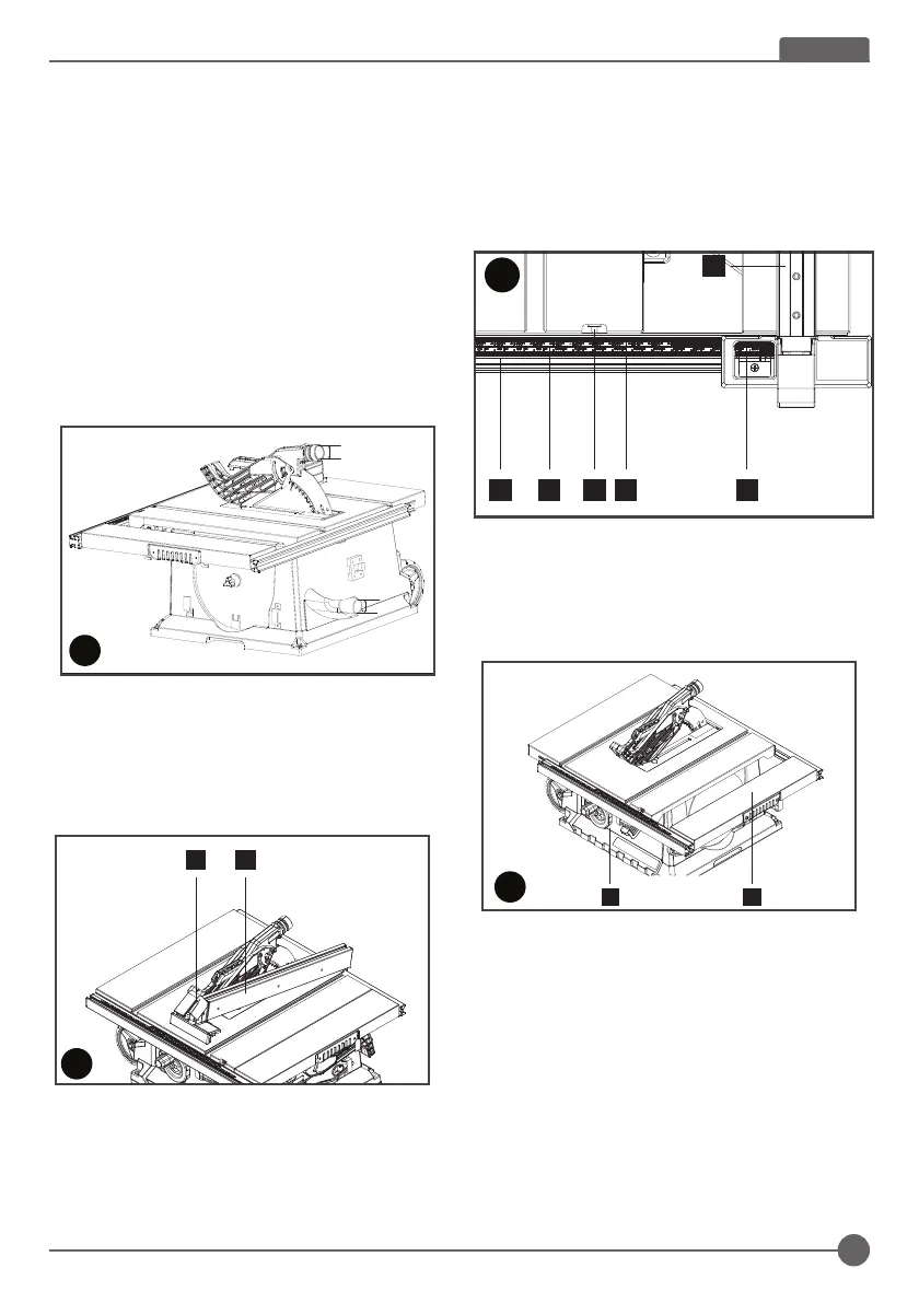
Saw blade assembly/replacement (Fig E, H, I)
1. WARNING: Ensure the machine is disconnected from the
power source. Wear the safety gloves.
2. Disassemble the saw blade guard (2) (Fig. H.)
3. Remove the table insert (20) (Fig. E).
4. Loosen the nut by placing the spanner wrench (17) on the
nut and countering with another spanner wrench (17) on
the flange (Fig. I).
5. WARNING! Turn the nut in the rotational direction of the
saw blade.
6. Remove the outer flange and take out the saw blade from
the inner flange, with diagonally downwards movement.
7. Carefully clean the flange with a cloth before fixing the
new saw blade.
8. Insert the new saw blade and fasten the outer flange. The
outer flange has a Φ25.4mm raised boss which fits in side
the blade bore.
WARNING! The teeth of a new blade are very sharp and can
be dangerous. Make sure the teeth point down at the front of
the table, aligned with the arrow marked on the saw blade
guard (2).
9. Attach the table insert (20) and the saw blade guard (2)
again and set them.
10. Before working, check the functionality of the guards.
On/Off switch (Fig. J)
- To switch the machine on, press the green start “I” button.
- To switch the machine off, press the red stop “O” button.
Cutting depth (Fig J)
Turn the blade elevation handle (11) to set the blade to the
required cutting depth.
4. The gap between the saw blade (4) teeth and the riving
knife should be around 3mm to 5mm (Fig.G)
5. R-tighten the mounting screw (f) and fix the table insert
(20)
WARNING! Ensure the machine is disconnected
from the power source. Never use the machine
without the table insert; Immediately replace the
table insert when worn or damaged
Saw blade guard assembly (Fig H)
1. Fasten the saw blade guard (2) to the riving knife (3) with
the bolt (g).
2. Disassembly in reverse order.
f
34
F
G
MAX 3-5
17
17
I
8
11
10
J
2 3
g
H
When the cutting width less than 300mm, means table no
extended, refer to scale (k). The red mark of sight-glass (m)
shows the required cutting width setup;
When cutting width more than 300mm need table extended,
refer to scale (l). Ensure the red mark of sight-glass (m) at
300mm and lock the rip fence, then the pointer (aa) aim at
scale (l) value shows the required cutting width setup.
Extension table (Fig N)
- The extension table (16) could be used for particularly
wide workpieces.
- Loosen the locking handle (14) and pull out the table width
extension.
- Turn anti-clockwise; to increase the cutting depth
- Turn Clockwise; to reduce the cutting depth
After each new adjustment it is advisable to carry out a trial
cut in order to check the set dimensions.
Setting the angle (Fig J)
Set the required bevel angle from 0 to 45 degree Before cutting,
ensure the saw blade (4) and mitre gauge (6) no collision
- Loose the Bevel adjustment locking knob (10).
- Set up the desired angle then lock the knob again.
Sawdust Collection (Fig K)
The machine is provided with a dust collection port at the rear
side for dia 35mm nozzle.
The blade guard assembly also features a dust collection port
for dia 35mm nozzle.
Rip fence mounting (Fig L)
- Fix the rip fence (5) at the back side and press the locking
handle (15) downwards.
- When disassembling, pull the locking handle up and
remove the rip fence (5).
- The rip fence could be locked setting with the rear knurled
nut.
Setting the cutting width (Fig. M)
- The rip fence (5) is used for lengthwise cutting of wood.
- Place the rip fence (5) on the guide rail (18) to the right or
left of the saw blade.
- 2 scales (k/l) on the guide rail (18) to show the gap
between fence rail and saw blade (4)
L
515
N
14 16
M
5
18 k l
aa
m
K
35mm
35mm
Rip fence mounting (Fig L)
- Fix the rip fence (5) at the back side and press the locking
handle (15) downwards.
- When disassembling, pull the locking handle up and
remove the rip fence (5).
-
The rip fence could be locked setting with the rear knurled nut.
Saw blade assembly/replacement (Fig E, H, I)
1. WARNING: Ensure the machine is disconnected from the
power source. Wear the safety gloves.
2. Disassemble the saw blade guard (2) (Fig. H.)
3. Remove the table insert (20) (Fig. E).
4. Loosen the nut by placing the spanner wrench (17) on the
nut and countering with another spanner wrench (17) on
the flange (Fig. I).
5. WARNING! Turn the nut in the rotational direction of the
saw blade.
6. Remove the outer flange and take out the saw blade from
the inner flange, with diagonally downwards movement.
7. Carefully clean the flange with a cloth before fixing the
new saw blade.
8. Insert the new saw blade and fasten the outer flange. The
outer flange has a Φ25.4mm raised boss which fits in side
the blade bore.
WARNING! The teeth of a new blade are very sharp and can
be dangerous. Make sure the teeth point down at the front of
the table, aligned with the arrow marked on the saw blade
guard (2).
9. Attach the table insert (20) and the saw blade guard (2)
again and set them.
10. Before working, check the functionality of the guards.
On/Off switch (Fig. J)
- To switch the machine on, press the green start “I” button.
- To switch the machine off, press the red stop “O” button.
Cutting depth (Fig J)
Turn the blade elevation handle (11) to set the blade to the
required cutting depth.
4. The gap between the saw blade (4) teeth and the riving
knife should be around 3mm to 5mm (Fig.G)
5. R-tighten the mounting screw (f) and fix the table insert
(20)
WARNING! Ensure the machine is disconnected
from the power source. Never use the machine
without the table insert; Immediately replace the
table insert when worn or damaged
Saw blade guard assembly (Fig H)
1. Fasten the saw blade guard (2) to the riving knife (3) with
the bolt (g).
2. Disassembly in reverse order.
f
34
F
G
MAX 3-5
17
17
I
8
11
10
J
2 3
g
H
When the cutting width less than 300mm, means table no
extended, refer to scale (k). The red mark of sight-glass (m)
shows the required cutting width setup;
When cutting width more than 300mm need table extended,
refer to scale (l). Ensure the red mark of sight-glass (m) at
300mm and lock the rip fence, then the pointer (aa) aim at
scale (l) value shows the required cutting width setup.
Extension table (Fig N)
- The extension table (16) could be used for particularly
wide workpieces.
- Loosen the locking handle (14) and pull out the table width
extension.
- Turn anti-clockwise; to increase the cutting depth
- Turn Clockwise; to reduce the cutting depth
After each new adjustment it is advisable to carry out a trial
cut in order to check the set dimensions.
Setting the angle (Fig J)
Set the required bevel angle from 0 to 45 degree Before cutting,
ensure the saw blade (4) and mitre gauge (6) no collision
- Loose the Bevel adjustment locking knob (10).
- Set up the desired angle then lock the knob again.
Sawdust Collection (Fig K)
The machine is provided with a dust collection port at the rear
side for dia 35mm nozzle.
The blade guard assembly also features a dust collection port
for dia 35mm nozzle.
Rip fence mounting (Fig L)
- Fix the rip fence (5) at the back side and press the locking
handle (15) downwards.
- When disassembling, pull the locking handle up and
remove the rip fence (5).
- The rip fence could be locked setting with the rear knurled
nut.
Setting the cutting width (Fig. M)
- The rip fence (5) is used for lengthwise cutting of wood.
- Place the rip fence (5) on the guide rail (18) to the right or
left of the saw blade.
- 2 scales (k/l) on the guide rail (18) to show the gap
between fence rail and saw blade (4)
L
515
N
14 16
M
5
18 k l
aa
m
K
35mm
35mm
Setting the cutting width (Fig. M)
- The rip fence (5) is used for lengthwise cutting of wood.
- Place the rip fence (5) on the guide rail (18) to the right or
left of the saw blade.
- 2 scales (k/l) on the guide rail (18) to show the gap
between fence rail and saw blade (4)
When the cutting width less than 300mm, means table no
extended, refer to scale (k). The red mark of sight-glass (m)
shows the required cutting width setup;
When cutting width more than 300mm need table extended,
refer to scale (l). Ensure the red mark of sight-glass (m) at
300mm and lock the rip fence, then the pointer (aa) aim at
scale (l) value shows the required cutting width setup.
Saw blade assembly/replacement (Fig E, H, I)
1. WARNING: Ensure the machine is disconnected from the
power source. Wear the safety gloves.
2. Disassemble the saw blade guard (2) (Fig. H.)
3. Remove the table insert (20) (Fig. E).
4. Loosen the nut by placing the spanner wrench (17) on the
nut and countering with another spanner wrench (17) on
the flange (Fig. I).
5. WARNING! Turn the nut in the rotational direction of the
saw blade.
6. Remove the outer flange and take out the saw blade from
the inner flange, with diagonally downwards movement.
7. Carefully clean the flange with a cloth before fixing the
new saw blade.
8. Insert the new saw blade and fasten the outer flange. The
outer flange has a Φ25.4mm raised boss which fits in side
the blade bore.
WARNING! The teeth of a new blade are very sharp and can
be dangerous. Make sure the teeth point down at the front of
the table, aligned with the arrow marked on the saw blade
guard (2).
9. Attach the table insert (20) and the saw blade guard (2)
again and set them.
10. Before working, check the functionality of the guards.
On/Off switch (Fig. J)
- To switch the machine on, press the green start “I” button.
- To switch the machine off, press the red stop “O” button.
Cutting depth (Fig J)
Turn the blade elevation handle (11) to set the blade to the
required cutting depth.
4. The gap between the saw blade (4) teeth and the riving
knife should be around 3mm to 5mm (Fig.G)
5. R-tighten the mounting screw (f) and fix the table insert
(20)
WARNING! Ensure the machine is disconnected
from the power source. Never use the machine
without the table insert; Immediately replace the
table insert when worn or damaged
Saw blade guard assembly (Fig H)
1. Fasten the saw blade guard (2) to the riving knife (3) with
the bolt (g).
2. Disassembly in reverse order.
f
34
F
G
MAX 3-5
17
17
I
8
11
10
J
2 3
g
H
When the cutting width less than 300mm, means table no
extended, refer to scale (k). The red mark of sight-glass (m)
shows the required cutting width setup;
When cutting width more than 300mm need table extended,
refer to scale (l). Ensure the red mark of sight-glass (m) at
300mm and lock the rip fence, then the pointer (aa) aim at
scale (l) value shows the required cutting width setup.
Extension table (Fig N)
- The extension table (16) could be used for particularly
wide workpieces.
- Loosen the locking handle (14) and pull out the table width
extension.
- Turn anti-clockwise; to increase the cutting depth
- Turn Clockwise; to reduce the cutting depth
After each new adjustment it is advisable to carry out a trial
cut in order to check the set dimensions.
Setting the angle (Fig J)
Set the required bevel angle from 0 to 45 degree Before cutting,
ensure the saw blade (4) and mitre gauge (6) no collision
- Loose the Bevel adjustment locking knob (10).
- Set up the desired angle then lock the knob again.
Sawdust Collection (Fig K)
The machine is provided with a dust collection port at the rear
side for dia 35mm nozzle.
The blade guard assembly also features a dust collection port
for dia 35mm nozzle.
Rip fence mounting (Fig L)
- Fix the rip fence (5) at the back side and press the locking
handle (15) downwards.
- When disassembling, pull the locking handle up and
remove the rip fence (5).
- The rip fence could be locked setting with the rear knurled
nut.
Setting the cutting width (Fig. M)
- The rip fence (5) is used for lengthwise cutting of wood.
- Place the rip fence (5) on the guide rail (18) to the right or
left of the saw blade.
- 2 scales (k/l) on the guide rail (18) to show the gap
between fence rail and saw blade (4)
L
515
N
14 16
M
5
18 k l
aa
m
Extension table (Fig N)
- The extension table (16) could be used for particularly
wide workpieces.
- Loosen the locking handle (14) and pull out the table
width extension.
Saw blade assembly/replacement (Fig E, H, I)
1. WARNING: Ensure the machine is disconnected from the
power source. Wear the safety gloves.
2. Disassemble the saw blade guard (2) (Fig. H.)
3. Remove the table insert (20) (Fig. E).
4. Loosen the nut by placing the spanner wrench (17) on the
nut and countering with another spanner wrench (17) on
the flange (Fig. I).
5. WARNING! Turn the nut in the rotational direction of the
saw blade.
6. Remove the outer flange and take out the saw blade from
the inner flange, with diagonally downwards movement.
7. Carefully clean the flange with a cloth before fixing the
new saw blade.
8. Insert the new saw blade and fasten the outer flange. The
outer flange has a Φ25.4mm raised boss which fits in side
the blade bore.
WARNING! The teeth of a new blade are very sharp and can
be dangerous. Make sure the teeth point down at the front of
the table, aligned with the arrow marked on the saw blade
guard (2).
9. Attach the table insert (20) and the saw blade guard (2)
again and set them.
10. Before working, check the functionality of the guards.
On/Off switch (Fig. J)
- To switch the machine on, press the green start “I” button.
- To switch the machine off, press the red stop “O” button.
Cutting depth (Fig J)
Turn the blade elevation handle (11) to set the blade to the
required cutting depth.
4. The gap between the saw blade (4) teeth and the riving
knife should be around 3mm to 5mm (Fig.G)
5. R-tighten the mounting screw (f) and fix the table insert
(20)
WARNING! Ensure the machine is disconnected
from the power source. Never use the machine
without the table insert; Immediately replace the
table insert when worn or damaged
Saw blade guard assembly (Fig H)
1. Fasten the saw blade guard (2) to the riving knife (3) with
the bolt (g).
2. Disassembly in reverse order.
f
34
F
G
MAX 3-5
17
17
I
8
11
10
J
2 3
g
H
When the cutting width less than 300mm, means table no
extended, refer to scale (k). The red mark of sight-glass (m)
shows the required cutting width setup;
When cutting width more than 300mm need table extended,
refer to scale (l). Ensure the red mark of sight-glass (m) at
300mm and lock the rip fence, then the pointer (aa) aim at
scale (l) value shows the required cutting width setup.
Extension table (Fig N)
- The extension table (16) could be used for particularly
wide workpieces.
- Loosen the locking handle (14) and pull out the table width
extension.
- Turn anti-clockwise; to increase the cutting depth
- Turn Clockwise; to reduce the cutting depth
After each new adjustment it is advisable to carry out a trial
cut in order to check the set dimensions.
Setting the angle (Fig J)
Set the required bevel angle from 0 to 45 degree Before cutting,
ensure the saw blade (4) and mitre gauge (6) no collision
- Loose the Bevel adjustment locking knob (10).
- Set up the desired angle then lock the knob again.
Sawdust Collection (Fig K)
The machine is provided with a dust collection port at the rear
side for dia 35mm nozzle.
The blade guard assembly also features a dust collection port
for dia 35mm nozzle.
Rip fence mounting (Fig L)
- Fix the rip fence (5) at the back side and press the locking
handle (15) downwards.
- When disassembling, pull the locking handle up and
remove the rip fence (5).
- The rip fence could be locked setting with the rear knurled
nut.
Setting the cutting width (Fig. M)
- The rip fence (5) is used for lengthwise cutting of wood.
- Place the rip fence (5) on the guide rail (18) to the right or
left of the saw blade.
- 2 scales (k/l) on the guide rail (18) to show the gap
between fence rail and saw blade (4)
L
515
N
14 16
11
ENGLISH
 Loading...