Saw blade assembly/replacement (Fig E, H, I)
1. WARNING: Ensure the machine is disconnected from the
power source. Wear the safety gloves.
2. Disassemble the saw blade guard (2) (Fig. H.)
3. Remove the table insert (20) (Fig. E).
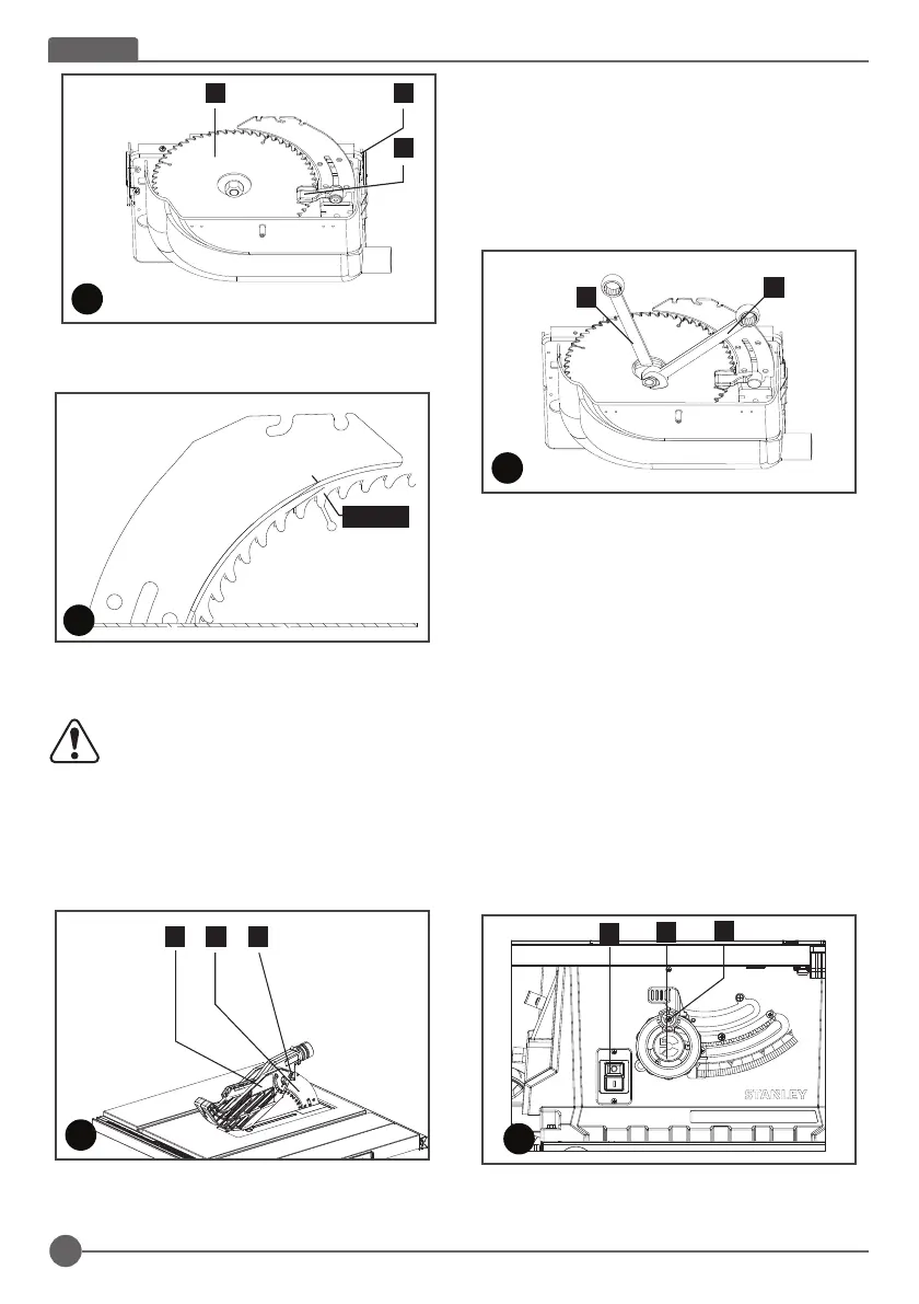
4. Loosen the nut by placing the spanner wrench (17) on the
nut and countering with another spanner wrench (17) on
the flange (Fig. I).
5. WARNING! Turn the nut in the rotational direction of the
saw blade.
6. Remove the outer flange and take out the saw blade from
the inner flange, with diagonally downwards movement.
7. Carefully clean the flange with a cloth before fixing the
new saw blade.
8. Insert the new saw blade and fasten the outer flange. The
outer flange has a Φ25.4mm raised boss which fits in side
the blade bore.
WARNING! The teeth of a new blade are very sharp and can
be dangerous. Make sure the teeth point down at the front of
the table, aligned with the arrow marked on the saw blade
guard (2).
9. Attach the table insert (20) and the saw blade guard (2)
again and set them.
10. Before working, check the functionality of the guards.
On/Off switch (Fig. J)
- To switch the machine on, press the green start “I” button.
- To switch the machine off, press the red stop “O” button.
Cutting depth (Fig J)
Turn the blade elevation handle (11) to set the blade to the
required cutting depth.
4. The gap between the saw blade (4) teeth and the riving
knife should be around 3mm to 5mm (Fig.G)
5. R-tighten the mounting screw (f) and fix the table insert
(20)
WARNING! Ensure the machine is disconnected
from the power source. Never use the machine
without the table insert; Immediately replace the
table insert when worn or damaged
Saw blade guard assembly (Fig H)
1. Fasten the saw blade guard (2) to the riving knife (3) with
the bolt (g).
2. Disassembly in reverse order.
f
34
F
4. The gap between the saw blade (4) teeth and the riving
knife should be around 3mm to 5mm (Fig.G)
10
ENGLISH
Saw blade assembly/replacement (Fig E, H, I)
1. WARNING: Ensure the machine is disconnected from the
power source. Wear the safety gloves.
2. Disassemble the saw blade guard (2) (Fig. H.)
3. Remove the table insert (20) (Fig. E).
4. Loosen the nut by placing the spanner wrench (17) on the
nut and countering with another spanner wrench (17) on
the flange (Fig. I).
5. WARNING! Turn the nut in the rotational direction of the
saw blade.
6. Remove the outer flange and take out the saw blade from
the inner flange, with diagonally downwards movement.
7. Carefully clean the flange with a cloth before fixing the
new saw blade.
8. Insert the new saw blade and fasten the outer flange. The
outer flange has a Φ25.4mm raised boss which fits in side
the blade bore.
WARNING! The teeth of a new blade are very sharp and can
be dangerous. Make sure the teeth point down at the front of
the table, aligned with the arrow marked on the saw blade
guard (2).
9. Attach the table insert (20) and the saw blade guard (2)
again and set them.
10. Before working, check the functionality of the guards.
On/Off switch (Fig. J)
- To switch the machine on, press the green start “I” button.
- To switch the machine off, press the red stop “O” button.
Cutting depth (Fig J)
Turn the blade elevation handle (11) to set the blade to the
required cutting depth.
4. The gap between the saw blade (4) teeth and the riving
knife should be around 3mm to 5mm (Fig.G)
5. R-tighten the mounting screw (f) and fix the table insert
(20)
WARNING! Ensure the machine is disconnected
from the power source. Never use the machine
without the table insert; Immediately replace the
table insert when worn or damaged
Saw blade guard assembly (Fig H)
1. Fasten the saw blade guard (2) to the riving knife (3) with
the bolt (g).
2. Disassembly in reverse order.
f
34
F
G
MAX 3-5
5. R-tighten the mounting screw (f) and fix the table insert
(20)
WARNING! Ensure the machine is disconnected
from the power source. Never use the machine
without the table insert; Immediately replace the
table insert when worn or damaged
Saw blade guard assembly (Fig H)
1. Fasten the saw blade guard (2) to the riving knife (3) with
the bolt (g).
2. Disassembly in reverse order.
10
ENGLISH
Saw blade assembly/replacement (Fig E, H, I)
1. WARNING: Ensure the machine is disconnected from the
power source. Wear the safety gloves.
2. Disassemble the saw blade guard (2) (Fig. H.)
3. Remove the table insert (20) (Fig. E).
4. Loosen the nut by placing the spanner wrench (17) on the
nut and countering with another spanner wrench (17) on
the flange (Fig. I).
5. WARNING! Turn the nut in the rotational direction of the
saw blade.
6. Remove the outer flange and take out the saw blade from
the inner flange, with diagonally downwards movement.
7. Carefully clean the flange with a cloth before fixing the
new saw blade.
8. Insert the new saw blade and fasten the outer flange. The
outer flange has a Φ25.4mm raised boss which fits in side
the blade bore.
WARNING! The teeth of a new blade are very sharp and can
be dangerous. Make sure the teeth point down at the front of
the table, aligned with the arrow marked on the saw blade
guard (2).
9. Attach the table insert (20) and the saw blade guard (2)
again and set them.
10. Before working, check the functionality of the guards.
On/Off switch (Fig. J)
- To switch the machine on, press the green start “I” button.
- To switch the machine off, press the red stop “O” button.
Cutting depth (Fig J)
Turn the blade elevation handle (11) to set the blade to the
required cutting depth.
4. The gap between the saw blade (4) teeth and the riving
knife should be around 3mm to 5mm (Fig.G)
5. R-tighten the mounting screw (f) and fix the table insert
(20)
WARNING! Ensure the machine is disconnected
from the power source. Never use the machine
without the table insert; Immediately replace the
table insert when worn or damaged
Saw blade guard assembly (Fig H)
1. Fasten the saw blade guard (2) to the riving knife (3) with
the bolt (g).
2. Disassembly in reverse order.
f
34
F
G
MAX 3-5
17
17
I
8
11
10
J
2 3
g
H
Saw blade assembly/replacement (Fig E, H, I)
1. WARNING: Ensure the machine is disconnected from the
power source. Wear the safety gloves.
2. Disassemble the saw blade guard (2) (Fig. H.)
3. Remove the table insert (20) (Fig. E).
4. Loosen the nut by placing the spanner wrench (17) on the
nut and countering with another spanner wrench (17) on
the flange (Fig. I).
10
ENGLISH
Saw blade assembly/replacement (Fig E, H, I)
1. WARNING: Ensure the machine is disconnected from the
power source. Wear the safety gloves.
2. Disassemble the saw blade guard (2) (Fig. H.)
3. Remove the table insert (20) (Fig. E).
4. Loosen the nut by placing the spanner wrench (17) on the
nut and countering with another spanner wrench (17) on
the flange (Fig. I).
5. WARNING! Turn the nut in the rotational direction of the
saw blade.
6. Remove the outer flange and take out the saw blade from
the inner flange, with diagonally downwards movement.
7. Carefully clean the flange with a cloth before fixing the
new saw blade.
8. Insert the new saw blade and fasten the outer flange. The
outer flange has a Φ25.4mm raised boss which fits in side
the blade bore.
WARNING! The teeth of a new blade are very sharp and can
be dangerous. Make sure the teeth point down at the front of
the table, aligned with the arrow marked on the saw blade
guard (2).
9. Attach the table insert (20) and the saw blade guard (2)
again and set them.
10. Before working, check the functionality of the guards.
On/Off switch (Fig. J)
- To switch the machine on, press the green start “I” button.
- To switch the machine off, press the red stop “O” button.
Cutting depth (Fig J)
Turn the blade elevation handle (11) to set the blade to the
required cutting depth.
4. The gap between the saw blade (4) teeth and the riving
knife should be around 3mm to 5mm (Fig.G)
5. R-tighten the mounting screw (f) and fix the table insert
(20)
WARNING! Ensure the machine is disconnected
from the power source. Never use the machine
without the table insert; Immediately replace the
table insert when worn or damaged
Saw blade guard assembly (Fig H)
1. Fasten the saw blade guard (2) to the riving knife (3) with
the bolt (g).
2. Disassembly in reverse order.
f
34
F
G
MAX 3-5
17
17
I
5. WARNING! Turn the nut in the rotational direction of the
saw blade.
6. Remove the outer flange and take out the saw blade from
the inner flange, with diagonally downwards movement.
7. Carefully clean the flange with a cloth before fixing the
new saw blade.
8. Insert the new saw blade and fasten the outer flange. The
outer flange has a Φ25.4mm raised boss which fits in
side the blade bore.
WARNING! The teeth of a new blade are very sharp and can be
dangerous. Make sure the teeth point down at the front of the
table, aligned with the arrow marked on the saw blade guard (2).
9. Attach the table insert (20) and the saw blade guard (2)
again and set them.
10. Before working, check the functionality of the guards.
On/Off switch (Fig. J)
- To switch the machine on, press the green start “I” button.
- To switch the machine off, press the red stop “O” button.
10
ENGLISH
Saw blade assembly/replacement (Fig E, H, I)
1. WARNING: Ensure the machine is disconnected from the
power source. Wear the safety gloves.
2. Disassemble the saw blade guard (2) (Fig. H.)
3. Remove the table insert (20) (Fig. E).
4. Loosen the nut by placing the spanner wrench (17) on the
nut and countering with another spanner wrench (17) on
the flange (Fig. I).
5. WARNING! Turn the nut in the rotational direction of the
saw blade.
6. Remove the outer flange and take out the saw blade from
the inner flange, with diagonally downwards movement.
7. Carefully clean the flange with a cloth before fixing the
new saw blade.
8. Insert the new saw blade and fasten the outer flange. The
outer flange has a Φ25.4mm raised boss which fits in side
the blade bore.
WARNING! The teeth of a new blade are very sharp and can
be dangerous. Make sure the teeth point down at the front of
the table, aligned with the arrow marked on the saw blade
guard (2).
9. Attach the table insert (20) and the saw blade guard (2)
again and set them.
10. Before working, check the functionality of the guards.
On/Off switch (Fig. J)
- To switch the machine on, press the green start “I” button.
- To switch the machine off, press the red stop “O” button.
Cutting depth (Fig J)
Turn the blade elevation handle (11) to set the blade to the
required cutting depth.
4. The gap between the saw blade (4) teeth and the riving
knife should be around 3mm to 5mm (Fig.G)
5. R-tighten the mounting screw (f) and fix the table insert
(20)
WARNING! Ensure the machine is disconnected
from the power source. Never use the machine
without the table insert; Immediately replace the
table insert when worn or damaged
Saw blade guard assembly (Fig H)
1. Fasten the saw blade guard (2) to the riving knife (3) with
the bolt (g).
2. Disassembly in reverse order.
f
34
F
G
MAX 3-5
17
17
I
8
11
10
J
Cutting depth (Fig J)
Turn the blade elevation handle (11) to set the blade to the
required cutting depth.
MAX 3-5
ENGLISH
10
 Loading...