Handle assembly (Fig D)
Place washer (e), housing (b), washer (c) and hex nut (d) on
the bolt (a) to assemble the handle (11)
uprights. Note that Part 2 should be positioned as shown in
Fig. B4. Connect Part 4 (top cross support) to the top of the
frame. Note that Part 4 should be positioned as shown in
Fig. B4.
Step 4
Now place and connect the ends of the top and center frame
supports to the frame. Take care to ensure that the supports
are positioned as shown in Fig. B5.
Step 5
Once you are satisfied that the frame is assembled correctly,
fully tighten ALL the bolts. Finally, assemble the 4 foot pads to
the bottom of each leg (see Fig. B6).
2. Assemble the stand’s legs
Step 1
Select the following parts:
2 x Part 1
1 x Part 3
1 x Part 5
Lay the parts together as shown in Fig. B1, B2, and B3. This
is best done by simply laying the parts loosely together on the
floor. Once you are satisfied that you have the parts correctly
laid together, start the fitting process.
Align the holes and secure with the bolts as shown in
Fig. B1.
DO NOT fully tighten the bolts, nuts and washers at this point.
Finger tight is sufficient.
Step 2
Repeat Step 1 so that there are two frames assembled.
Step 3
Select the following parts:
2 x Part 2
2 x Part 4
These will form the crosspieces between the previously
assembled frames. Lay the parts flat on the floor. Connect the
longer Part (2) and fix it to the frame in the center of the
B1
B2
B3
B1
5
3
2
4
B4
1
B6
5
1
4
B5
Handle assembly (Fig D)
Place washer (e), housing (b), washer (c) and hex nut (d) on
the bolt (a) to assemble the handle (11)
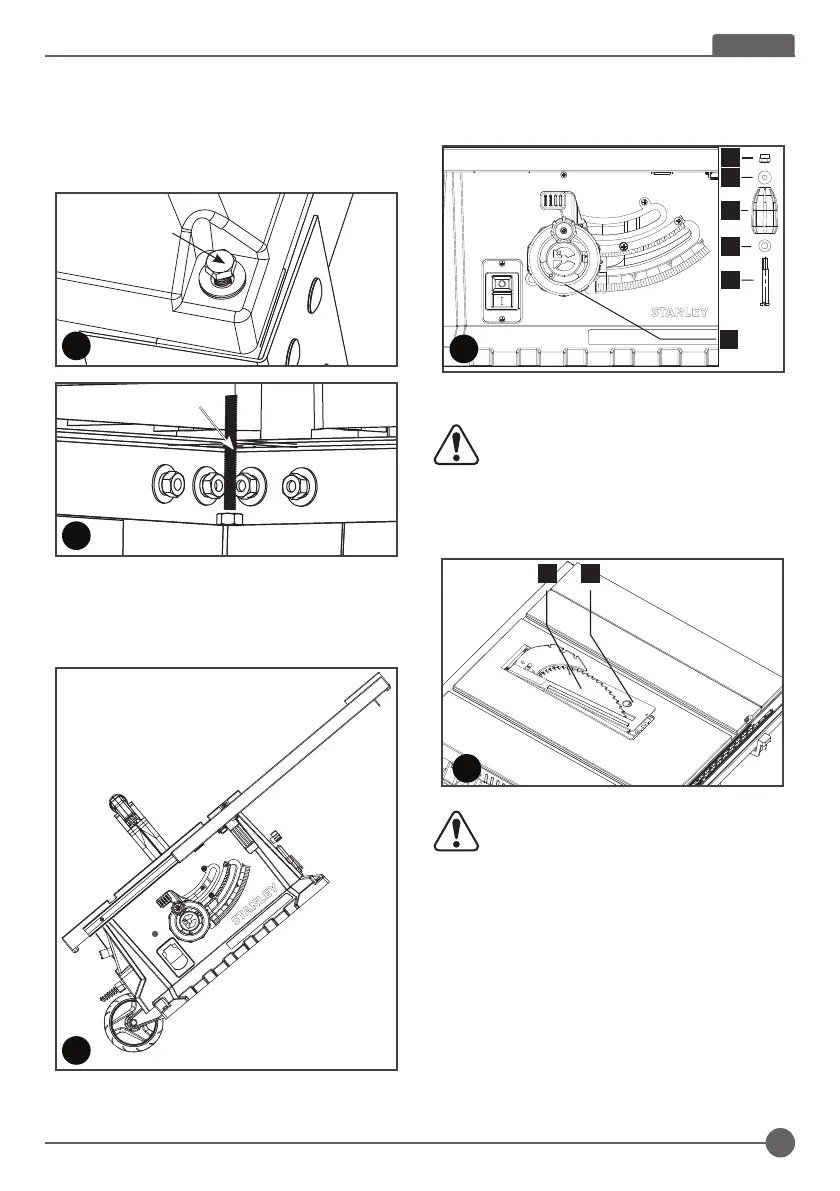
Riving knife set-up (Fig E, F, G)
WARNING! Disconnect the mains cable! The
setup of the riving knife (3) must be checked
before each use.
1. Set the saw blade (4) to the max. cutting depth, put it at 00
position and lock it
2. Remove the table insert (20) (Fig. E)
WARNING! For transport reasons, the riving
knife (3) was fixed in the lower position before
initial commissioning. Only work with the
machine if the riving knife (3) is in the upper
position. Fitting the riving knife (3) in the upper
position is as follows:
3. Loosen the locking handle (f) and push the riving knife (3)
in the upper position (Fig.F)
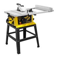
Fitting the table saw to the stand (see FIG. C1, C2)
There are four mounting holes on the base of the saw. 4
corresponding mounting holes are located on the top plane of
the stand. Put the table saw on the stand, match the holes on
the base of the saw with the holes on the stand, and secure
them with the 4 bolts (12) provided. DO fully fasten
Transportation (Fig C3)
Pull out the right side extension as the temporary handle to
transport the table saw on its wheels."
12
C1
12
C2
C3
d
c
e
a
11
D
b
Riving knife set-up (Fig E, F, G)
WARNING! Disconnect the mains cable! The
setup of the riving knife (3) must be checked
before each use.
1. Set the saw blade (4) to the max. cutting depth, put it at
00 position and lock it
2. Remove the table insert (20) (Fig. E)
uprights. Note that Part 2 should be positioned as shown in
Fig. B4. Connect Part 4 (top cross support) to the top of the
frame. Note that Part 4 should be positioned as shown in
Fig. B4.
Step 4
Now place and connect the ends of the top and center frame
supports to the frame. Take care to ensure that the supports
are positioned as shown in Fig. B5.
Step 5
Once you are satisfied that the frame is assembled correctly,
fully tighten ALL the bolts. Finally, assemble the 4 foot pads to
the bottom of each leg (see Fig. B6).
2. Assemble the stand’s legs
Step 1
Select the following parts:
2 x Part 1
1 x Part 3
1 x Part 5
Lay the parts together as shown in Fig. B1, B2, and B3. This
is best done by simply laying the parts loosely together on the
floor. Once you are satisfied that you have the parts correctly
laid together, start the fitting process.
Align the holes and secure with the bolts as shown in
Fig. B1.
DO NOT fully tighten the bolts, nuts and washers at this point.
Finger tight is sufficient.
Step 2
Repeat Step 1 so that there are two frames assembled.
Step 3
Select the following parts:
2 x Part 2
2 x Part 4
These will form the crosspieces between the previously
assembled frames. Lay the parts flat on the floor. Connect the
longer Part (2) and fix it to the frame in the center of the
B1
B2
B3
B1
5
3
2
4
B4
1
B6
5
1
4
B5
Handle assembly (Fig D)
Place washer (e), housing (b), washer (c) and hex nut (d) on
the bolt (a) to assemble the handle (11)
Riving knife set-up (Fig E, F, G)
WARNING! Disconnect the mains cable! The
setup of the riving knife (3) must be checked
before each use.
1. Set the saw blade (4) to the max. cutting depth, put it at 00
position and lock it
2. Remove the table insert (20) (Fig. E)
WARNING! For transport reasons, the riving
knife (3) was fixed in the lower position before
initial commissioning. Only work with the
machine if the riving knife (3) is in the upper
position. Fitting the riving knife (3) in the upper
position is as follows:
3. Loosen the locking handle (f) and push the riving knife (3)
in the upper position (Fig.F)
Fitting the table saw to the stand (see FIG. C1, C2)
There are four mounting holes on the base of the saw. 4
corresponding mounting holes are located on the top plane of
the stand. Put the table saw on the stand, match the holes on
the base of the saw with the holes on the stand, and secure
them with the 4 bolts (12) provided. DO fully fasten
Transportation (Fig C3)
Pull out the right side extension as the temporary handle to
transport the table saw on its wheels."
12
C1
12
C2
C3
d
c
e
a
11
D
b
204
E
WARNING! For transport reasons, the riving
knife (3) was fixed in the lower position before
initial commissioning. Only work with the
machine if the riving knife (3) is in the upper
position. Fitting the riving knife (3) in the upper
position is as follows:
3. Loosen the locking handle (f) and push the riving knife (3)
in the upper position (Fig.F)
Fitting the table saw to the stand (see FIG. C1, C2)
There are four mounting holes on the base of the saw. 4
corresponding mounting holes are located on the top plane of
the stand. Put the table saw on the stand, match the holes on
the base of the saw with the holes on the stand, and secure
them with the 4 bolts (12) provided. DO fully fasten
uprights. Note that Part 2 should be positioned as shown in
Fig. B4. Connect Part 4 (top cross support) to the top of the
frame. Note that Part 4 should be positioned as shown in
Fig. B4.
Step 4
Now place and connect the ends of the top and center frame
supports to the frame. Take care to ensure that the supports
are positioned as shown in Fig. B5.
Step 5
Once you are satisfied that the frame is assembled correctly,
fully tighten ALL the bolts. Finally, assemble the 4 foot pads to
the bottom of each leg (see Fig. B6).
2. Assemble the stand’s legs
Step 1
Select the following parts:
2 x Part 1
1 x Part 3
1 x Part 5
Lay the parts together as shown in Fig. B1, B2, and B3. This
is best done by simply laying the parts loosely together on the
floor. Once you are satisfied that you have the parts correctly
laid together, start the fitting process.
Align the holes and secure with the bolts as shown in
Fig. B1.
DO NOT fully tighten the bolts, nuts and washers at this point.
Finger tight is sufficient.
Step 2
Repeat Step 1 so that there are two frames assembled.
Step 3
Select the following parts:
2 x Part 2
2 x Part 4
These will form the crosspieces between the previously
assembled frames. Lay the parts flat on the floor. Connect the
longer Part (2) and fix it to the frame in the center of the
B1
B2
B3
B1
5
3
2
4
B4
1
B6
5
1
4
B5
Handle assembly (Fig D)
Place washer (e), housing (b), washer (c) and hex nut (d) on
the bolt (a) to assemble the handle (11)
Riving knife set-up (Fig E, F, G)
WARNING! Disconnect the mains cable! The
setup of the riving knife (3) must be checked
before each use.
1. Set the saw blade (4) to the max. cutting depth, put it at 00
position and lock it
2. Remove the table insert (20) (Fig. E)
WARNING! For transport reasons, the riving
knife (3) was fixed in the lower position before
initial commissioning. Only work with the
machine if the riving knife (3) is in the upper
position. Fitting the riving knife (3) in the upper
position is as follows:
3. Loosen the locking handle (f) and push the riving knife (3)
in the upper position (Fig.F)
Fitting the table saw to the stand (see FIG. C1, C2)
There are four mounting holes on the base of the saw. 4
corresponding mounting holes are located on the top plane of
the stand. Put the table saw on the stand, match the holes on
the base of the saw with the holes on the stand, and secure
them with the 4 bolts (12) provided. DO fully fasten
Transportation (Fig C3)
Pull out the right side extension as the temporary handle to
transport the table saw on its wheels."
12
C1
12
C2
Transportation (Fig C3)
Pull out the right side extension as the temporary handle to
transport the table saw on its wheels.
uprights. Note that Part 2 should be positioned as shown in
Fig. B4. Connect Part 4 (top cross support) to the top of the
frame. Note that Part 4 should be positioned as shown in
Fig. B4.
Step 4
Now place and connect the ends of the top and center frame
supports to the frame. Take care to ensure that the supports
are positioned as shown in Fig. B5.
Step 5
Once you are satisfied that the frame is assembled correctly,
fully tighten ALL the bolts. Finally, assemble the 4 foot pads to
the bottom of each leg (see Fig. B6).
2. Assemble the stand’s legs
Step 1
Select the following parts:
2 x Part 1
1 x Part 3
1 x Part 5
Lay the parts together as shown in Fig. B1, B2, and B3. This
is best done by simply laying the parts loosely together on the
floor. Once you are satisfied that you have the parts correctly
laid together, start the fitting process.
Align the holes and secure with the bolts as shown in
Fig. B1.
DO NOT fully tighten the bolts, nuts and washers at this point.
Finger tight is sufficient.
Step 2
Repeat Step 1 so that there are two frames assembled.
Step 3
Select the following parts:
2 x Part 2
2 x Part 4
These will form the crosspieces between the previously
assembled frames. Lay the parts flat on the floor. Connect the
longer Part (2) and fix it to the frame in the center of the
B1
B2
B3
B1
5
3
2
4
B4
1
B6
5
1
4
B5
Handle assembly (Fig D)
Place washer (e), housing (b), washer (c) and hex nut (d) on
the bolt (a) to assemble the handle (11)
Riving knife set-up (Fig E, F, G)
WARNING! Disconnect the mains cable! The
setup of the riving knife (3) must be checked
before each use.
1. Set the saw blade (4) to the max. cutting depth, put it at 00
position and lock it
2. Remove the table insert (20) (Fig. E)
WARNING! For transport reasons, the riving
knife (3) was fixed in the lower position before
initial commissioning. Only work with the
machine if the riving knife (3) is in the upper
position. Fitting the riving knife (3) in the upper
position is as follows:
3. Loosen the locking handle (f) and push the riving knife (3)
in the upper position (Fig.F)
Fitting the table saw to the stand (see FIG. C1, C2)
There are four mounting holes on the base of the saw. 4
corresponding mounting holes are located on the top plane of
the stand. Put the table saw on the stand, match the holes on
the base of the saw with the holes on the stand, and secure
them with the 4 bolts (12) provided. DO fully fasten
Transportation (Fig C3)
Pull out the right side extension as the temporary handle to
transport the table saw on its wheels."
12
C1
12
C2
C3
9
ENGLISH
 Loading...