Ghép các bộ phận với nhau như được minh họa
trong Hình B1, B2, và B3. Bạn có thể dễ dàng
hoàn thành tốt công đoạn này bằng cách đặt các
bộ phận cùng nhau trên sàn. Khi bạn đã chắc rằng
mình có các bộ phận đã được đặt chính xác cùng
nhau, hãy bắt đầu quá trình lắp ráp.
Chỉnh các lỗ thẳng nhau và cố định bằng bu lông
như được minh họa trong Hình. B1.
KHÔNG vặn chặt hết bu lông, đai ốc và vòng đệm
tại bước này. Vặn tay là đủ.
Bước 2
Lặp lại bước 1 để lắp được hai khung.
8
ENGLISH
uprights. Note that Part 2 should be positioned as shown in
Fig. B4. Connect Part 4 (top cross support) to the top of the
frame. Note that Part 4 should be positioned as shown in
Fig. B4.
Step 4
Now place and connect the ends of the top and center frame
supports to the frame. Take care to ensure that the supports
are positioned as shown in Fig. B5.
Step 5
Once you are satisfied that the frame is assembled correctly,
fully tighten ALL the bolts. Finally, assemble the 4 foot pads to
the bottom of each leg (see Fig. B6).
2. Assemble the stand’s legs
Step 1
Select the following parts:
2 x Part 1
1 x Part 3
1 x Part 5
Lay the parts together as shown in Fig. B1, B2, and B3. This
is best done by simply laying the parts loosely together on the
floor. Once you are satisfied that you have the parts correctly
laid together, start the fitting process.
Align the holes and secure with the bolts as shown in
Fig. B1.
DO NOT fully tighten the bolts, nuts and washers at this point.
Finger tight is sufficient.
Step 2
Repeat Step 1 so that there are two frames assembled.
Step 3
Select the following parts:
2 x Part 2
2 x Part 4
These will form the crosspieces between the previously
assembled frames. Lay the parts flat on the floor. Connect the
longer Part (2) and fix it to the frame in the center of the
B1
B2
B3
B1
Bước 3
Chọn các bộ phận sau:
2 x Bộ phận 2
2 x Bộ phận 4
Các bộ phận này sẽ tạo thành các thanh ngang
giữa các khung được lắp ráp trước đó. Đặt các bộ
phận xuống sàn. Nối Bộ phận (2) dài hơn và gắn
19. Que đẩy
20. Bộ phận chèn bàn
21. Rãnh (a)
21. Rãnh (b)
22. Bộ phận bảo vệ quá tải
LẮP RÁP
Lắp ráp giá có chân
Khi lắp ráp giá đỡ, bạn chỉ nên vặn nhẹ vít cho
đến khi giá đỡ được lắp ráp đầy đủ.
1. Nhận dạng các bộ phận và phụ tùng
Trước khi bạn bắt đầu lắp ráp các chân của giá
đỡ, hãy dỡ hoàn toàn cưa và đặt các bộ phận
tách rời nhau.
Nhận dạng rõ ràng các bộ phận được minh
họa trong Hình A1 và A2, bao gồm các bộ
phận để lắp ghép. Nhóm các bộ phận này với
nhau và đảm bảo rằng bạn có đủ số lượng các
bộ phận.
• The maximunm speed of the saw blade shall always be
greater than or at least equal to the speed marked on the
rating plate of the tool.
• The saw blade diameter must be in accordance with the
markings on rating plate of the tool.
• Consider applying specially designed noisereduction
blades.
• Do not use high steel (HS) saw blades.
• Do not use cracked or damaged saw blades.
• Ensure that the chosen saw blade is suitable for the
material to be cut.
• Always wear gloves for handling saw blades and rough
material. Saw blades should be carried in a holder
wherever practicable.
Power connections
Before connecting the machine to the power line, make sure
the switch (8) is in the “OFF” position and be sure that the
electric current is of the same characteristics as indicated on
the machine. All line connections should make good contact.
Running on low voltage will damage the machine.
DANGER! Do not expose the machine to rain or
operate the machine in damp locations.
Before connecting the machine to the power source, make
sure the switch is in the “OFF” position.
SAFETY OF OTHERS
• This appliance is not intended for use by persons
(including children) with reduced physical, sensory or
mental capabilities, or lack of experience and knowledge,
unless they have been given supervision or instruction
concerning use of the appliance by a person responsible
for their safety.
• Children should be supervised to ensure that they do not
play with the appliance.
RESIDUAL RISKS
Additional residual risks may arise when using the tool which
may not be included in the enclosed safety warnings. These
risks can arise from misuse, prolonged use etc. In spite of the
application of the relevant safety regulations and the
implementation of safety devices, certain risks cannot be
avoided. These are:
• Injuries caused when changing any parts, blades or
accessories.
• Injuries caused by prolonged use of a tool. When using
any tool for prolonged periods ensure you take regular
breaks.
• Impairment of hearing.
• Health hazards caused by breathing dust developed when
using your tool (example: working with wood, especially
oak, beech and MDF.)
ELECTRICAL SAFETY
Your tool needs to be earthed. Always check that the main
voltage corresponds to the voltage on the rating plate.
WARNING
! If the power cord is damaged, it must
be replaced by the manufacturer, authorized
STANLEY Service Center or an equally qualified
person in order to avoid damage or injury. If the
power cord is replaced by an equally qualified
person, but not authorized by STANLEY, the
warranty will not be valid.
USING AN EXTENSION CABLE
If it is necessary to use an extension cable, please use an
approved extension cable that fits the tool’s power input
specifications. The minimum cross-sectional area of the
conducting wire is 1.5 sq. mm. Cables should be untangled
before reeling up.
Cable cross-sectional
area (mm
2
)
Cable rated current
(Ampere)
0.75 6
1.00 10
1.50 15
2.50 20
4.00 25
Voltage Amperes Cable rated current (Ampere)
110-127 0 - 2.0 6 6 6 6 6 10
2.1 - 3.4 6 6 6 6 15 15
3.5 - 5.0 6 6 10 15 20 20
5.1 - 7.0 10 10 15 20 20 25
7.1 - 12.0 15 15 20 25 25 -
12.1 - 20.0 20 20 25 - - -
220-240 0 - 2.0 6 6 6 6 6 6
2.1 - 3.4 6 6 6 6 6 6
3.5 - 5.0 6 6 6 6 10 15
5.1 - 7.0 10 10 10 10 15 15
7.1 - 12.0 15 15 15 15 20 20
12.1 - 20.0 20 20 20 20 25 -
Cable length (m)
7.5 15 25 30 45 60
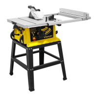
8. On/Off switch
9. Leg stand
10. Bevel adjustment locking knob
11. Blade elevation handle
12. Leg stand locking bolt
13. Blade tilting wheel
14. Locking handle for extension table
15. Locking handle for rip fence
16. Extension table
17. Spanner wrench
18. Guide rail
19. Push stick
20. Table insert
21. Groove (a)
21. Groove (b)
22. Overloaded protector
ASSEMBLY
Assembly of the leg stand
When assembling the stand, it is recommended that the
screws are only lightly tightened until the stand is fully
assembled.
1. Identify the parts and fittings
Before you start the assembly of the stand’s legs, fully
unpack the saw and lay out the individual parts.
Clearly identify the parts shown in Fig. A1 and A2,
including the fittings. Group these parts together and
ensure that you have the correct quantity of all the
pieces shown.
LABELS ON TOOL
The label on your tool may include the following symbols:
Position of Date Code
The Date Code, which also includes the year of manufacture,
is printed into the housing.
Example:
2017 XX JN
Year of manufacturing
PACKAGE CONTENTS
The package contains:
1 table saw
1 60T saw blade
1 Blade guard
1 Miter gauge
1 Rip fence
2 Spanner wrench
1 Push stick
1 Instruction manual
• Check for damage to the tool, parts or accessories which
may have occurred during transport.
• Take the time to thoroughly read and understand this
manual prior to operation.
FEATURES (Fig. A)
This tool includes some or all of the following features.
1. Saw table
2. Blade guard
3. Riving knife
4. Saw blade
5. Rip fence
6. Mitre guage
7. Transportation wheels
WARNING! To reduce the risk of injury, the user
must read the instruction manual before use.
Wear ear protection.
Wear safety glasses or goggles.
V Volts Direct Current
A Amperes n
0
No-Load Speed
Hz Hertz Class II Construction
W Watts
Earthing Terminal
min minutes
Safety Alert Symbol
Alternating
Current
/min.
Revolutions or
Reciprocation per
minute
Bolt Washer Nut
A2
5
5
3
3
1
1
1
1
2
2
4
4
1 x 4 pieces
2 x 2 pieces
5 x 2 pieces
3 x 2 pieces
4 x 2 pieces
A1
1. Lắp ráp chân của giá đỡ
Bước 1
Chọn các bộ phận sau:
2 x Bộ phận 1
1 x Bộ phận 3
1 x Bộ phận 5
1 x 4 thanh
2 x 2 thanh
3 x 2 thanh
4 x 2 thanh
5 x 2 thanh
Bu lông Vòng đệm Đai ốc
63
TIẾNG VIỆT
 Loading...