CAUTION: Be careful not to pinch the display cable between the display
assembly and the neck of the Stepper.
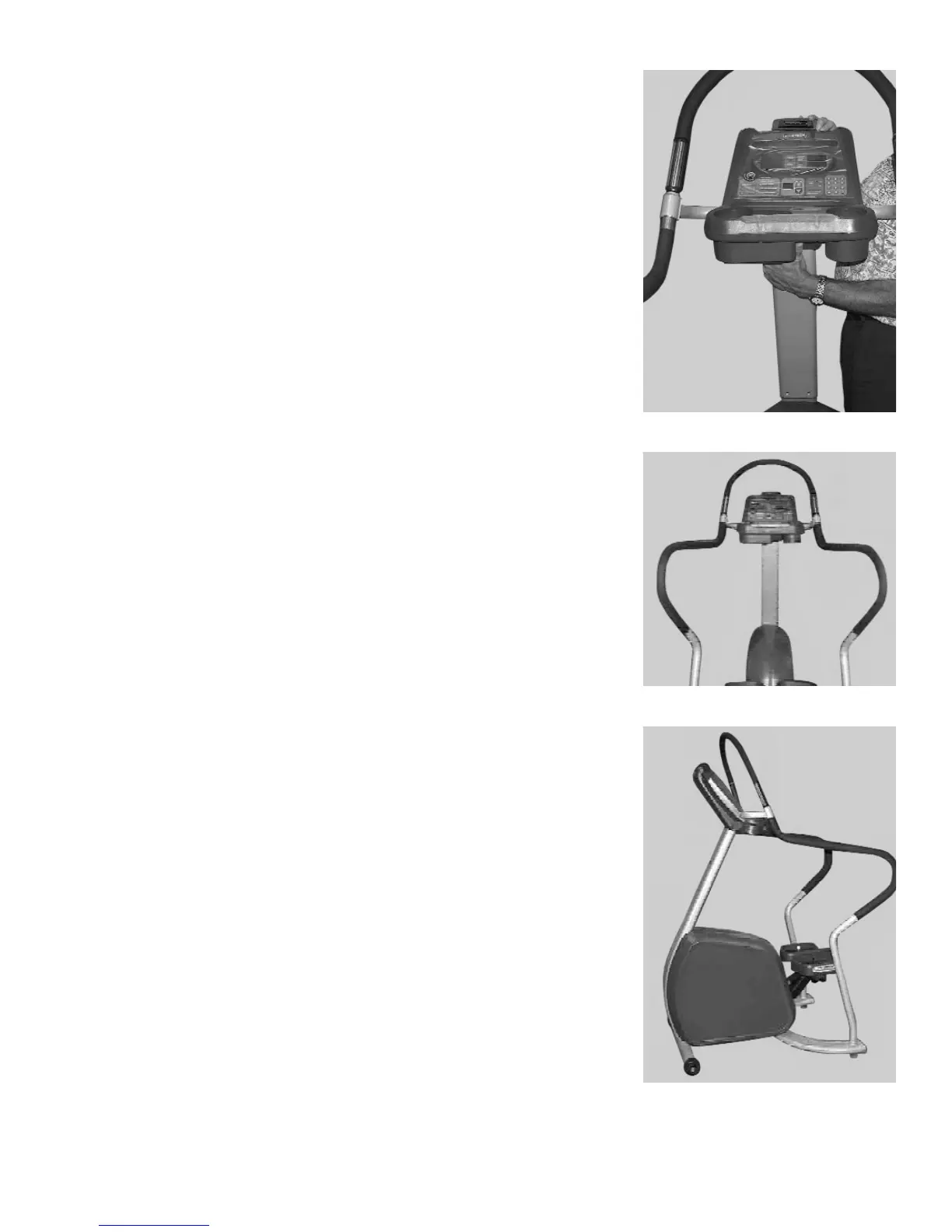
Slide the display assembly onto the neck of the Stepper, making sure both side
handrails (installed in step 2) properly engage the display assembly handrail.
Thread two handrail screws, PN 110-0506, into each side handrail.
Use the 5/32" hex key, PN 290-0040, and secure the display assembly to the
neck of the Stepper with four neck screws, PN 110-3172.
Use the 5/32" hex key, PN 290-0040, and fully tighten the eight handrail
screws (four at each handrail).
4. Final Assembly and Testing
Check all screws to ensure they are tightened securely.
Make sure the side handrails are tight.
Mount the Stepper, begin stepping, and verify that the display panel turns on.
Operate the unit to check for proper operation.
You have now completed assembly of your STAR TRAC PRO STEPPER.
14 STAR TRAC PRO STEPPER O
WNER
’
S
M
ANUAL
Step 3B
Step 3C
Step 4