4 5
IL1104
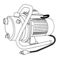
Water Level
25 ft.
Max
Suction
Lift
3/4 or 1 in.
Discharge Pipe
1-1/4 in.
Suction
Pipe
Discharge
to Home
Pipe
Support
Foot Valve
TYPICAL PUMP SETUP
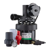
Shallow well jet pumps are designed for use
where the suction lift is 25 feet or less. They can
be used with drilled (cased wells) (Fig. 1), dug
wells, driven wells (Fig. 2) or with cisterns or
lakes.
VENTILATION
Ventilation and drainage must be provided to
prevent damage to the motor from heat and
moisture.
FREEZING
The pump and all piping must be protected from
freezing. If freezing weather is forecast, drain
pump or remove completely from the system.
WATER SUPPLY
The water source must be able to supply enough
water to satisfy the capacity of the pump and
water needs. See performance chart on page 2.
SUCTION LIFT
Suction lift is the vertical distance from the lowest
level of the water to the pump intake. The pump
will move water as long as the pump is within 25
vertical feet of the water source.
HORIZONTAL DISTANCE
The horizontal distance is the horizontal
measurement between the pump suction and the
water source. This distance may affect the ability
of the pump to operate. If it is over 100 feet, call
the manufacturer for assistance at
1-800-742-5044.
PIPE AND FITTINGS
Use galvanized steel or NSF PW Schedule 40
PVC pipe and ttings. This material is designed
for water pressure and will seal against air and
water under pressure. Do Not Use: DWV ttings,
as these are designed for drains without pressure
and will not seal properly. (Fig. 2 & 3)
CAUTION: The entire system must be
air and water tight for efcient operation and to
maintain prime.
WIRE SIZE:
The wire size is determined by the distance from
the power source to the pump motor, and the
horsepower rating of the motor. See the wire chart
on page 11 for proper wire size.
GENERAL PUMP INFORMATION
1
L0951
IL1105
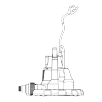
3/4 in. Discharge
1-1/4 in.
Suction
3
TOOLS REQUIRED
PREPARATION
Pipe wrenches (2)
Wire strippers
Needle-nose pliers
Phillips screwdriver
Wire cutters
Adjustable wrench
Pipe tape
Pipe dope
PARTS YOU MAY NEED FOR ASSEMBLY
(not included) (Fig. 1)
Item Description
1 1-1/4 In. union
2 1-1/4 in. adapter
3 1-1/4 in. elbow
4 3/4 in. union
5 1 in. adapter
6 1 in. x 3/4 in. reducer bushing
7 3/4 in. adapter
8 1 in. elbow
9 1-1/4 in. check valve
10 3/4 in. tee (plastic)
11 3/4 in. tee (steel)
12 3/4 in. x 3 in. nipple (steel)
13 3/4 in. plug (steel)
14 Foot valve
Electric cord strain relief
OPTIONAL PARTS FOR ASSEMBLY
(not included) (Fig 2)
Item Description
1 Ball Valve (plastic)
2 3/4 in. x 1/4 in. bushing (steel)
3 Pressure Gauge
4 Pump stand for tank
NOTE: For a successful installation, take time to study your application for the correct pipe size and
appropriate ttings. The illustrations in these instructions will assist you with required and optional
ttings. Sch. 40 PVC plastic pipe and ttings were used in these instructions.
Before beginning installation of product, make sure all parts are present. If any part is missing
or damaged, do not attempt to assemble the product. Contact customer service for replacement
parts.
Estimated Installation Time: 2 hours.
1
IL1383
l
ı
ı
ı
l
ı
ı
ı
ı
l
ı
ı
ı
l
ı
ı
ı
ı
l
ı
ı
ı
l
ı
ı
ı
l
ı
ı
ı
l
ı
ı
ı
ı
l
ı
ı
ı
l
ı
ı
ı
ı
l
ı
ı
ı
l
ı
ı
ı
ı
200
80
160
140
120
100
80
60
40
20
1
2
4
3
2
IL0068
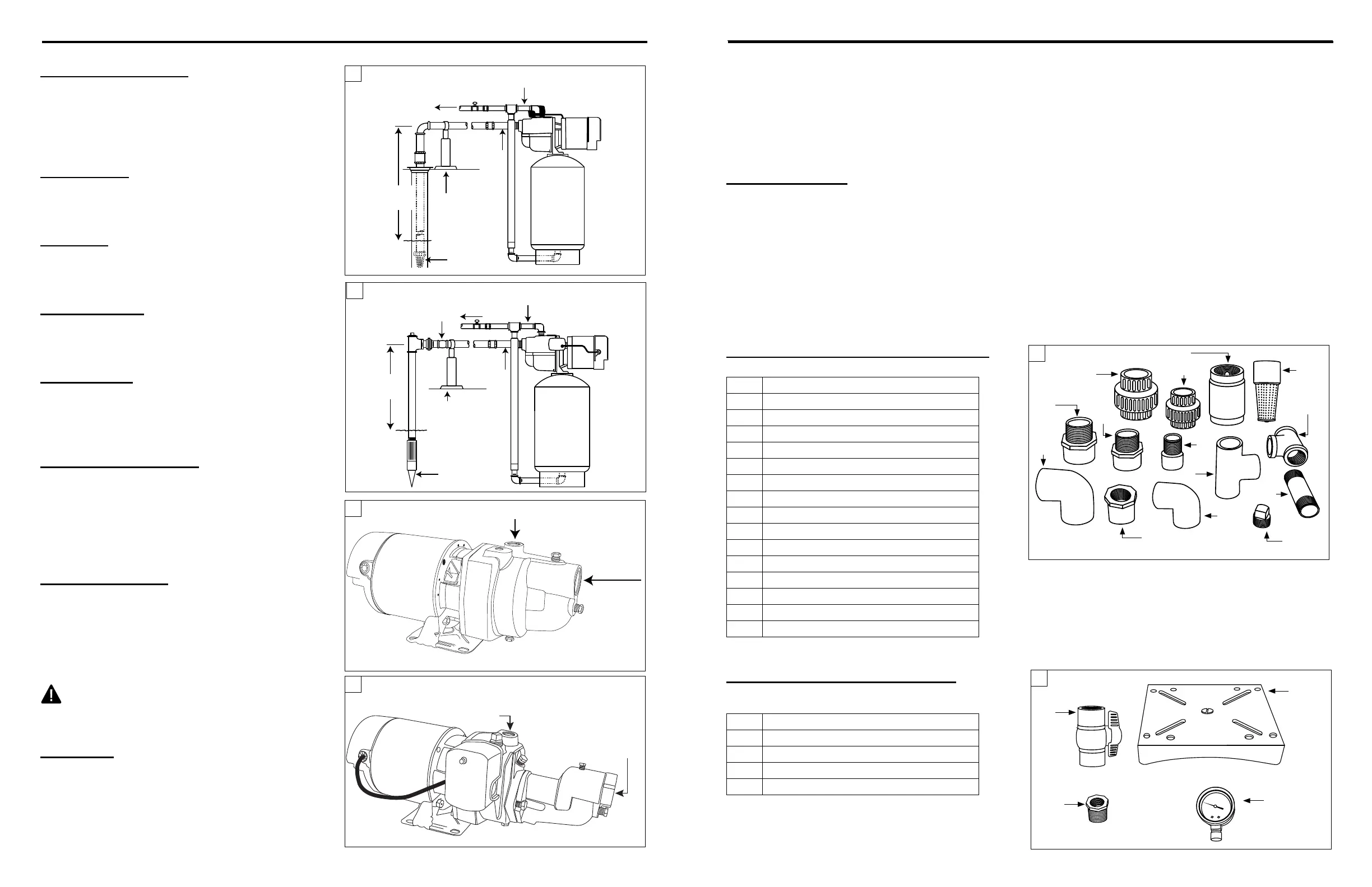
3/4 or 1 in.
Discharge
1-1/4 in.
Suction
4
JHU10S, EK10S, CPH05S, JHU15S
ES05S, EK05S,
ES07S, EK07S
IL1472
Water Level
25 ft.
Max
Suction
Lift
3/4 or 1 in.
Discharge Pipe
1-1/4 in.
Suction
Pipe
Discharge
to Home
Pipe
Support
Drive Point
Check
Valve
2
IL1382
12
1
4
9
14
11
13
8
10
7
6
5
3
2
 Loading...