Stavoklima s.r.o. | www.stavoklima.cz | DITRONIC-MANUAL | 21
En
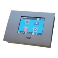
DITRONIC-MANUAL
UNPACKING - INSTALLATION
The Ditronic controller is available as a set with a room sensor, quick
start guide, user manual, and installation accessories (dowels, screws),
and a drill template. First, please check correct cable type *(recommen-
ded cable type is UTP – 8 wires; e.g. ROLINE U125H424- A, and more),
then attach the drill template to mark the drilling holes. Make sure the
cable is located correctly as shown on the template. Then, drill Ø 8mm
holes for the dowels, fit the dowels and screws according to the drill tem-
plate (Fig. 1). Screw the screws almost completely to the wall with about
1.5mm clearance to fix the controller anchoring plate (Fig. 2).
TABLE OF CONTENTS:
Unpacking page. 21
Installation page. 22
Controller and system description page. 23
User and service functions setup page. 24-35
MODBUS communication interface page. 36