22 | Stavoklima s.r.o. | www.stavoklima.cz | DITRONIC-MANUAL
DRILL TEMPLATE INCLUDED FIG. 1
CONTROLLER WALL MOUNTING included) Fig. 2
CONNECTION OF 8PIN CONNECTOR (not included) Fig. 3
DITRONIC - DRILL TEMPLATE
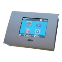
DITRONIC
CABLE
SCREWS 4,0x30
MODBUS
CABLE
Now, shorten the 8-wire cable to about 10cm from the wall, and crimp the cable
connector. Please pay attention to proper arrangement of the wires, see Fig. 3
(identical on both cable ends). Slide the connector to the socket inside the cont-
roller before fitting the controller on the wall. Make sure the cable does not cross
the outline of the anchoring plate. Slide the controller with the anchoring plate on
the screws and push down to finish the installation. As a security feature you can
tighten the screws now (Fig. 2).
DITRONIC-MANUAL
En