37
742.114 | 14.50
EN
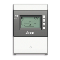
10.3.6 Heat quantity
B
Calculates the acquired heat volume based on the following information:
• Supply temperature
• Return temperature
• Flow rate determined using the following methods:
– Calculated via pump speed
– Measured using a pulse water meter (terminal 5)
Notes
– Calculation based on the pump speed cannot be performed
when No system (system 0.1) has been selected.
– In drainback systems, the correct flow rate value can only be
read when the system is filled.
• Glycol proportion and accounting for the temperature dependent
thermophysical properties of the heat transfer fluid
Additional possibility: display of the amount of CO
2
saved by using the
system. The amount of CO
2
is calculated from the acquired heat volume.
To do this, the controller requires the conversion factor lbs
CO2
/kWh
therm
to be entered.
Display Characteristic min. max.
Factory
setting
Activation on, oFF
oFF
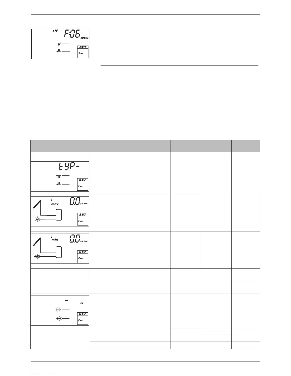
Type of flow rate acquisition tyP 1, tyP 2
1)
–
l
g
Type 1: flow rate value at max.
speed F
max.
(pump 1).
When the Fig. at the left is dis-
played (value flashes), then enter
the value read from the flow rate
display.
F
min.
999.9
gal/min
0.0 gal/min
l
g
Type 1: flow rate value at min.
speed F
min.
(pump 1).
When the Fig. at the left is dis-
played (value flashes), then enter
the value read from the flow rate
display.
0.0 gal/min F
max.
0.0 gal/min
Type 1: flow rate value at max.
speed F
max.
(pump 2)
2)
F
min.
999.9
gal/min
0.0 gal/min
Type 1: flow rate value at min.
speed F
min.
(pump 2)
2)
0.0 gal/min F
max.
0.0 gal/min
l
g
Type 2: flow rate of the pulse
water meter in litres/pulse; see
the pulse water meter data
sheet.
1.0 gal...10.0 gal,
1 l, 10 l, 25 l
– gal
(no flow
rate value
selected)
Glycol proportion 0% 60% 40%
Supply sensor input (warm) 1 ... 5 –
Return sensor input (cold) 1 ... 5 –