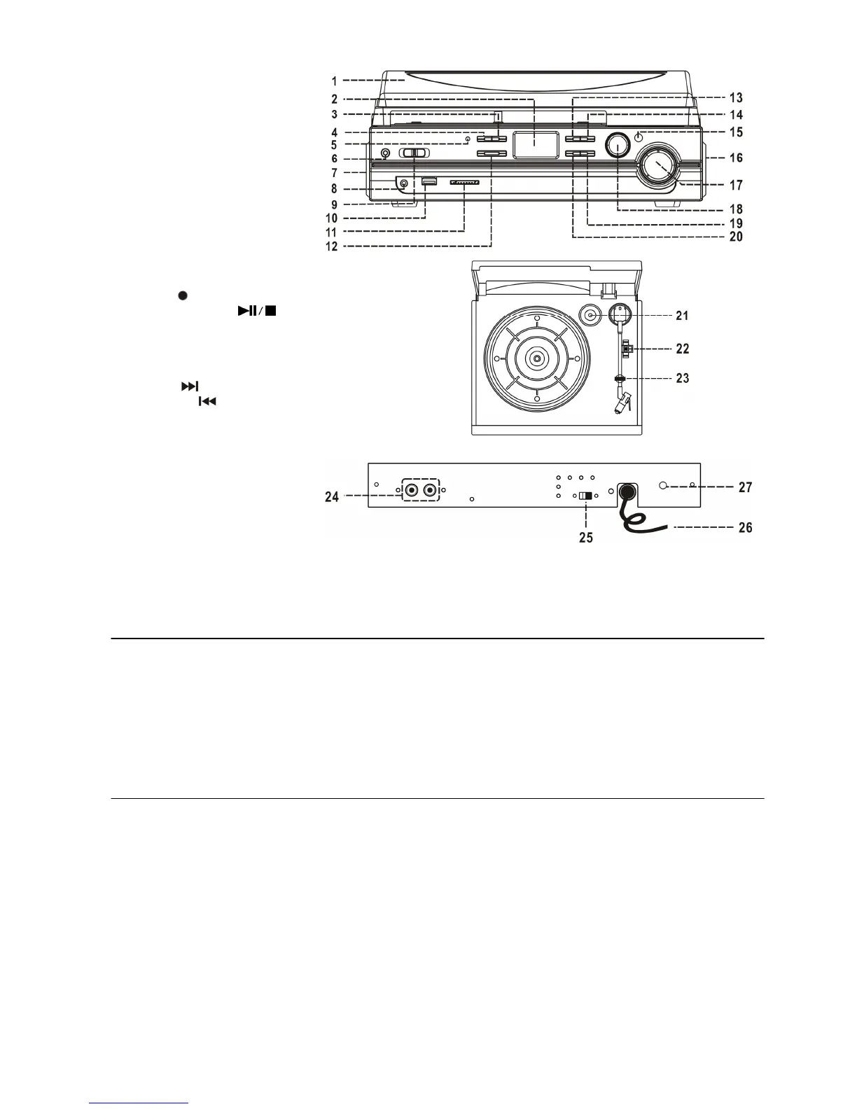
LOCATION OF CONTROLS
1) Dust Cover
2) LCD Display
3) MP3 Folder Up Button
4) Source Button
5) Power LED Indicator
6) 3.5mm dia. Aux-In Jack
7) Left Speaker
8) 3.5mm dia. headphone Jack
9) Function Selector
(Aux-Phono-USB/SD)
10) USB Port
11) SD/MMC Card Slot
12) X-Bass On/Off Button
13) Record
Button
14) Play/Pause/Stop
Button
15) Remote Control Sensor
16) Right Speaker
17) Power On/Off-Volume knob
18) Pitch Adjustment Knob
19) Skip Up
Button
20) Skip Down
Button
21) 45rpm Spindle Adaptor
22) Turntable Speed Selector
23) Tone Arm Rest
24) Line Out Socket (RCA)
25) Auto Stop On/Off Switch
26) AC Power Cord
27) Subwoofer Socket
CAUTION:
Usage of controls or adjustments or performance of procedures other than those specified herein may result in
hazardous radiation exposure.
This unit should not be adjusted, modified or repaired by anyone except qualified service personnel.
PRECAUTIONS FOR USE
INSTALLATION
• Unpack all parts and remove protective material. Please keep all packaging until you have fully checked all
parts of the unit are working correctly and for future use, in case the unit needs servicing.
• Please ensure the Remote Control has been located before storing the packaging.
• This unit is operated by 230V/50Hz AC Mains only. Do not connect the unit to the mains before checking
the mains voltage is correct for your home and before all other connections have been made.
• When positioning the unit, never cover any vents and make sure that there is a space of several centimeters
around the unit for ventilation.
CONNECTION
1. Connect the Power Cord (26) to a 230V AC Mains Power outlet.
2. Turn the POWER-VOL Knob (17) in a clockwise direction until the red Power LED Indicator (5) and the blue
LCD Display backlight (2) light up. This indicates the unit is correctly connected to the mains power supply.
3. Your system is now ready for use.
4. Switch the Function Selector (9) to “AUX/PHONO or USB/SD” position and, depending on the position of this
switch, the display will show “AUX”, “PHONO” or “NO USB”.
E-1