Installation as Draft-Mounting with Bulkhead Fitting 41
English
9.1 Support Construction
9.1.1 Required Materials
The following materials are not included
in the delivery:
• welding block
• seals, bolts, nuts and washers for the
flanges and junction box
• seat flange - according to the bulkhead
flange
• duct for the sensor cable
• output cable - shielded, multicore
• stop-valve - according to the flange on
the sensor.
• if not included in the delivery: junction
box and bulkhead flange.
9.1.2 Support Installation
1. Fix the seat flange to the upper end of
the cable duct.
2. Install the cable duct.
• Minimum distance
cable <--> heating coils: 1m
3. Install the welding block or the inside
of the outer hull.
• The welding block may be installed at
any position below the minimum
draft.
• The welding block should be placed
in a place with the least possible tur-
bulences.
The installation with a stop valve is
recommended to enable main-
tenance works without draining the
tank.
9.2 Installation of Sensor
1. Remove and dispose of the packaging.
2. Check the delivery for damage and
consistency.
3. Check that the tank name on the label
at the end of the cable corresponds
with the designated tank.
4. Ensure that the mounting thread is
clean and free of damage.
5. Check the O-ring at the end of the sen-
sor for damages.
6. Screw in the mounting thread of the
sensor into the sensor flange.
7. Tighten the sensor with an open-end
wrench. (tightening torque: 25 Nm)
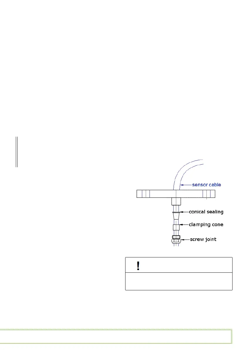
8.Assemble the bulkhead flange on the
sensor cable.
9. Put the sensor and cable through the
cable duct.
CAUTION
Only install the device while it is not
under current or pressure.


 To Next Page