Panel Controls and Terminals
UR242 Operation Manual 17
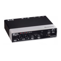
Controls and Functions
Common to Compressor and Equalizer
1 MORPH
Adjusts the parameter of the Sweet Spot Data. You can
simultaneously adjust the compressor and equalizer
settings which are set to five points around this knob by
turning this knob. When you set the knob between two
adjacent points, the compressor and equalizer settings will
be set to an intermediate value.
2 Sweet Spot Data
Selects the Sweet Spot Data.
3 TOTAL GAIN
Adjusts the total gain of the Channel Strip.
Range: -18.0 dB – +18.0 dB
4 Level Meter
Indicates the output level of the Channel Strip.
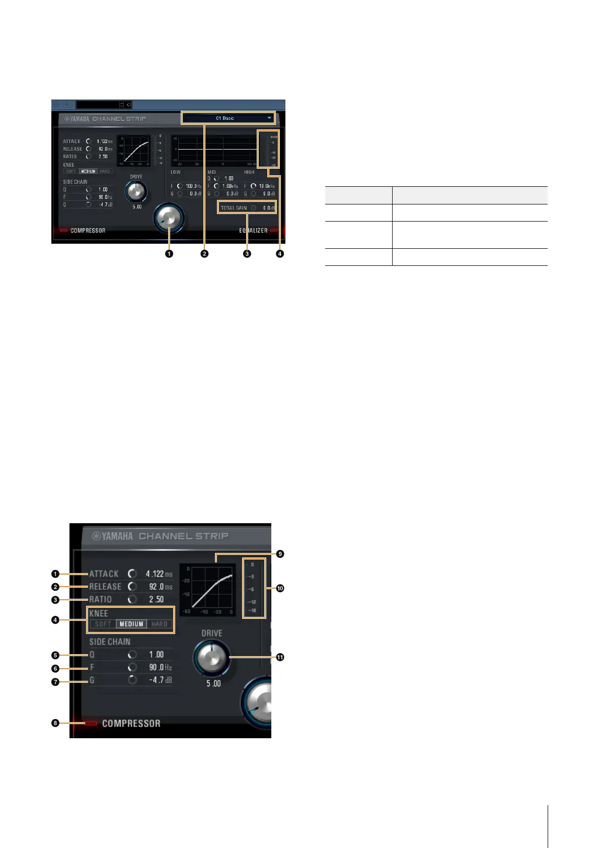
Compressor
1 ATTAC K
Adjusts the attack time of the compressor.
Range: 0.092 msec – 80.00 msec
2 RELEASE
Adjusts the release time of the compressor.
Range: 9.3 msec – 999.0 msec
3 RATIO
Adjusts the ratio of the compressor.
Range: 1.00 – ∞
4 KNEE
Selects the knee type of the compressor.
5 SIDE CHAIN Q
Adjusts the band width of the side chain filter.
Range: 0.50 – 16.00
6 SIDE CHAIN F
Adjusts the center frequency of the side chain filter.
Range: 20.0 Hz – 20.0 kHz
7 SIDE CHAIN G
Adjusts the gain of the side chain filter.
Range: -18.0 dB – +18.0 dB
8 COMPRESSOR On/Off
Turns the compressor on (lit) and off (dark).
9 Compressor Curve
This graph indicates the approximate compressor
response. The vertical axis indicates the output signal
level, and the horizontal axis indicates the input signal
level.
) Gain Reduction Meter
Indicates the gain reduction.
! DRIVE
Adjusts the degree to which the compressor is applied. The
higher the value, the greater the effect.
Range: 0.00 – 10.00
Options Description
SOFT Produces the most gradual change.
MEDIUM Results in a setting midway between SOFT
and HARD.
HARD Produces the sharpest change.