28
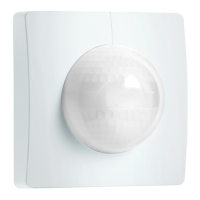
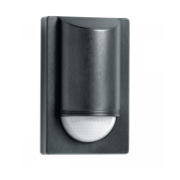
For mounting the IS3180 on the wall, a condensation water drainage hole (Ø 5 mm
drill bit) is marked next to the rubber seal. This must be opened if necessary.
Connection examples (Fig� 4�2)
a Load with control input
b Supply the load with L�
L and S1 must be connected in the sensor�
5� Mounting
• Check all components for damage.
• Do not use the product if it is damaged.
• Select an appropriate mounting location, taking the reach and motion detection
into consideration.
Procedure for installing concealed power supply lead (Fig� 5�1)
Procedure for installing surface-mounted power supply lead (Fig� 5�2)
IS3360, IS3360 MX Highbay, IS345, IS345Highbay
Procedure for installing concealed power supply lead (wall mounting) IS3180
(Fig� 5�3)
Switch OFF power supply.
• Detach designer trim from sensor module.
• Disconnect sensor module from the load module.
• Connect to mains power supply.
– Surface-mounted power supply lead (Fig� 5�4)
– Concealed power supply lead (Fig� 5�5)
• Insert fastening screw and mount load module.


 To Next Page