INSSTE402NP1010
WARNING
Before installing and operating this product,
the owner and/or installer must read,
understand and follow these instructions and
keep them handy for future reference. If these
instructions are not followed, the warranty
will be considered null and void and the
manufacturer deems no further responsibility
for this product. Moreover, the following
instructions must be adhered to in order to
avoid personal injuries or property damages,
serious injuries and potentially fatal electric
shocks. All electric connections must be made
by a qualified electrician, according to the
electric and building codes effective in
your region. Do NOT connect this product
to a supply source other than 120 VAC, 208
VAC or 240 VAC, and do not exceed the load
limits specified. Protect the heating system
with the appropriate circuit breaker or fuse.
You must regularly clean dirt accumulations
on the thermostat. Do NOT use fluid to clean
thermostat air vents
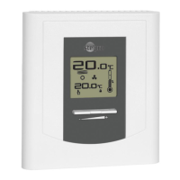
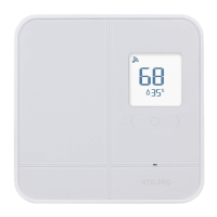
1. Description
The electronic thermostat STE402NP can be
used to control electric heating units such as
electric baseboards, convectors, or aerocon-
vectors. It keeps the temperature of a room at
the requested set point with a high degree of
accuracy. This product is designed for instal-
lations with electrical current - with a resistive
load - ranging from 1.2 A to 16.7 A (150 to
2000 W at 120 VAC, 260 to 3475 at 208 VAC
and 300 to 4000 W at 240 VAC).
This thermostat is not compatible with the
following installations
•electrical current higher than 16.7 A with a
resistive load (4000 W @ 240 VAC, 3475 W @
208 VAC and 2000 W @ 120 VAC);
•electrical current lower than 1.2 A with a
resistive load (300 W @ 240 VAC, 260 W @
208 VAC and 150 W @ 120 VAC);
•inductiveload(presenceof acontactorora
relay); and
•centralheatingsystem.
Parts supplied:
•one(1)thermostat;
•two(2)mountingscrews;
•two (2) solderless connectors suitable for
copper wires.
Note:
This handling description is printed prior to product
development. When a part of the product specifi-
cation must be changed to improve operability or
other functions, priority is given to the product
specification itself. In such instances, the instruc-
tion manual may not entirely match all the functions
of the actual product.
Therefore, the actual product and packaging, as
well as the name and illustration, may differ from
the manual.
The screen/LCD display shown as an example in
this manual may be different from the actual screen/
LCD display.
2