2112 116TH AVE NE SUITE 1-5, BELLEVUE WA, 98004 WWW.STEPPIR.COM TEL: (425)-453-1910 FAX: (425)-462-4415
11
TEST MOTORS
The “Test Motor” function is only used during the installation of the antenna. It provides for
testing the control cable wiring before final assembly and raising the antenna. If you are rais-
ing the antenna with the control cable attached it is a good way to check that you have con-
nected all of the element cables correctly.
If you are not going to connect the control cable and test it on the ground make sure you
have the element control cables positively identified and well marked (DIR2, DVR, REF etc) .
If you get the elements mixed up on the terminal block you will get very confusing results
such as, high SWR, low performance, etc. Mark the cables coming from each element box
with colored electrical tape or a felt pen. Mark them before you tape them along the boom, it
is very easy to get two parallel wires mixed up. Now when you are on the tower it will be
easy to identify each element control cable positively.
For the MonstIR only DO NOT use the Test Motor unless you have the first two sections com-
pleted and attached on each of the three large (70’) element housings (DIR2 DVR REF)
because approximately 20’ of copper will be feed out of each side. This will allow you to see
the copper tape just peek out of the 3/4” CPVC liner tube.
When performing the Test Motor NONE of the 18’ telescoping poles should be installed at this
point or you won’t see the tape extend out approximately 1” to 4”. This test allows you to ver-
ify that each element is indeed the one the controller thinks it is and that it is wired correctly
(not running backwards). If there is copper sticking out at the end of testing any element, the
motor for that element is wired wrong. The stepper motors will run backwards if you swap the
wires on either one of the motor windings.
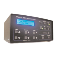
Before connecting the 25 pin connector on the control cable to the controller, plug in the con-
troller and turn it on. The screen should read “Ham Mode Elements Home”. If it does not run
the “Retract Elements” function (Reference this manual). The screen will indicate that it is
homing the elements and finish with “Ham Mode Elements Home”. It is now safe to connect
the 25 pin connector on the control cable to the controller.
In the case of the Remote Driver Board Option the element can be tested while the antenna
is on the ground. With the provided crossover cable that came with the Remote Driver
Board Option plug the controller to the remote driver board at the base of the tower via the
“Remote” CAT 5 plug. Do plug the 25 pin D sub connector to the controller to test or operate
the antenna. Refer to Remote Driver Board section for more information.
WARNING: Do NOT select any of the band buttons at this time. Without the 18’ poles
installed, if any of the band buttons are selected, the copper tape will come out of all the ele-
ment housings onto the ground. This could result in damage to the copper tape requiring fac-
tory repair.
Check to see if there is any copper tape sticking out of any of the element housings. If there
is copper sticking out run the “Calibrate” function and this will bring the tape home (Reference
this manual).

 Loading...