3 Operation
7
3.1 Quartz Multispeed Timer
Drive (QMT)
The Quartz Multispeed Timer unit (QMT) is
designed to operate from 6 alkaline "D" cell
batteries, which were included with the
recorder when shipped. To install the
batteries, first be sure the timer switch is
set to the "OFF" position. Remove the
QMT cover by sliding the latching plate on
the front cover to the right. Check that the
battery contacts are clean.
Observing the polarity markings in the case
(see guide, Figure 5) place the six batteries
in the main body of the timer. Note the
batteries should alternate polarity direction.
Replace the QMT cover and re-latch.
NOTE:
BE SURE THAT THE
BATTERIES ARE INSTALLED
PROPERLY (ALTERNATING POLARITY).
IF ALL BATTERIES ARE REVERSED,
THE TIMER WILL NOT RUN. HOWEVER,
IF ONLY ONE BATTERY IS REVERSED,
THE TIMER WILL RUN, BUT OVERALL
BATTERY LIFE WILL BE GREATLY
REDUCED.
Set the speed select switches to the fastest
chart speed. At this speed, the timer motor
will be pulsed approximately once a
second. By listening closely, you should
be able to hear a short, "clicking" sound
each time the motor is pulsed. If you hear
this sound, the clock is operating properly.
Set the timer to the desired chart speed to
begin recording.
If desired, the QMT can be powered from
an external source, such as a lead-acid
battery or AC power converter. Any power
source supplying 8 to 14 VDC with a peak
current capability of 300 mA can be used
to power the timer.
NOTE:
THE TIMER SHOULD NEVER
BE CONNECTED TO AN EXTERNAL
POWER SOURCE WHILE
SIMULTANEOUSLY USING INTERNAL
BATTERIES.
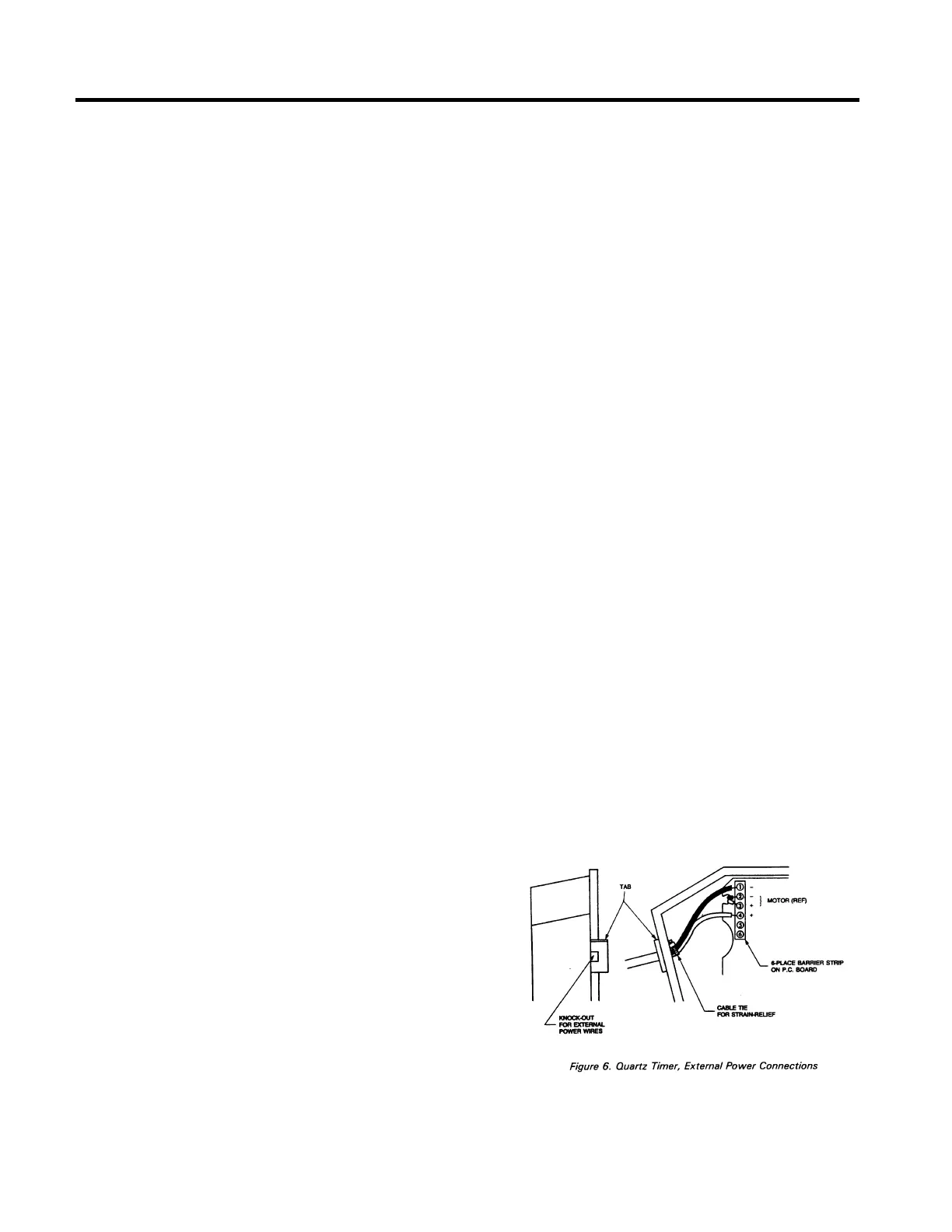
Remove the QMT cover by sliding the
latching plate on the front cover to the right
and remove all batteries. Referring to
Figure 6, remove the knock-out from the
main body, using a small screwdriver or
awl. Select an appropriate 2-wire cable (or
two individual wires) for the power
connection. Note: the wires should NOT
be connected to a power source while
doing this installation. Prepare the cable
end for connection to the QMT by stripping
back each wire about 6mm (1/4 in.).
Thread the cable through the knock-out as
shown in Figure 6. Loosen terminal
connection 1 and 4 on the QMT terminal
strip. Insert the negative (-) wire into
terminal 1 and the positive (+)into terminal
4. The existing wires need not be
removed. Tighten the terminal screws
back down.
If the external power source is to be
located outside the Type A Recorder,
remove the 6mm (1/1 4 in.) hole plug and
run the cable through the recorder base to
the external source.
 Loading...