3 Operation
5
Check the final position of the recorder to
be sure the float and counterweight can
move up and down freely, without
interference from the side of the well or any
protuberances. Secure the recorder to the
mounting surface with screws, using the
holes in the recorder feet.
2.4 Installing the Chart
Rotate the pen off the chart. Pull the
friction roller assembly away from the chart
cylinder. Lock it in place by sliding it in the
direction of the "lock" arrow. Remove the
two thumb screw from the sides of the
writing plate and lift the plate out. Remove
the take-up cylinder from the recorder.
Remove the supply cylinder (middle
cylinder) from the recorder, and remove
the large knurled nut from the end.
Observe that the core of the new chart is
flush at one end and protrudes at the other.
Slip the chart onto the supply cylinder,
flush end toward the flange, and tighten the
knurled nut firmly in place. Place the
supply cylinder in its bearings, with the
flange to the left so the chart comes off of
the top of the cylinder. Replace the take-
up cylinder.
Pass the chart behind the drive cylinder
(bottom drum) and out between the
cylinder and the friction rollers. Pull the
chart upward about 1 1/2 inches beyond
the take-up cylinder with the right edge
square to the flange. Reinstall the writing
plate. Pass the chart over the writing plate
and around the front of the take-up
cylinder. Install the half-round paper clamp
from the bottom, pressing downward.
Take the slack out of the chart by winding
the take-up cylinder upward, using the
white knurled flange. Rotate the take-up
cylinder until the chart and pen are
properly positioned for the desired start
point for recording. Unlock the friction
roller assembly and allow it to hold the
paper in place.
2.5 Removing the Chart
Lift the pen from the chart drive cylinder by
simply tilting it back. Pull the friction roller
aware from the chart and slide it in the
direction of the "Lock" arrow. Manually
advance the chart by turning the large,
white knurled disk on the left end of the
take-up cylinder. Do this until the graphic
record is just beyond the edge of the
writing plate. Using the edge of the writing
plate as a guide, cut the chart with a knife.
Lift the take-up cylinder out of the
instrument and slip off the chart. This may
require a firm twisting motion if the chart is
tightly wound. Pull or shake the chart
clamp out of the chart roll. Re-attach the
remaining chart, or install a new chart as
described in section 1.6, above. The A-10
(English) charts have a diagonal blue line
marked at the end of the chart fastened to
the core. When this line appears during
use, the remaining days of supply can be
calculated. On the A-10 chart, count the
number of small divisions (0.1 in) between
the left margin and the blue line. At a chart
speed of 2.4 inches per day, the number of
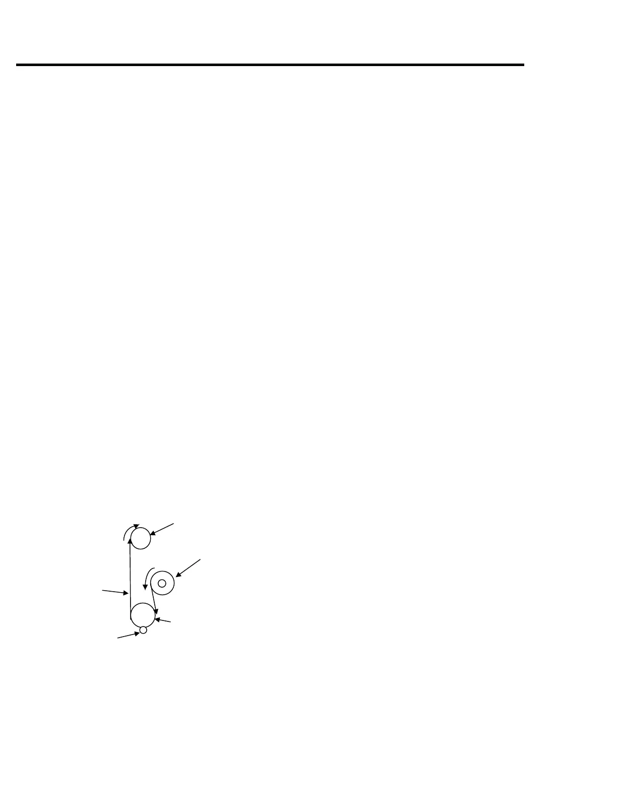
Take-up Cylinder
Supply Cylinder
Advance Cylinder
Friction
Roller
Chart
Figure 3. Chart Routing