3 Operation
9
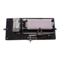
between the adjustable arm's pivot screws.
Be careful not to tighten the pivot screws
too tight so as to bind the stylus arm.
The disposable cartridge pen clips into the
pen holder on the stylus arm. It is protected
by a plastic cover over the pen tip. Place
the pen in the clip, making sure it locks
firmly into place. Check for proper pen
position with reference to time and stage
level. Then remove the cover from the tip
to begin recording.
The stylus can be adjusted to insure that
reversals occur at the margin of the chart.
Loosen the adjusting arm clamp screw.
Reposition the arm and tighten the clamp
screw. It is best to align the stylus for
reversal on the left margin line, as chart
expansion due to humidity changes will
occur at the right side (the left edge of the
chart is against the flange on the take-up
and supply cylinders).
3.3 Gage Scales
Gage scales may be reconfigured by
changing either the float pulley size
or the float pulley standard, or both
(see Table 2 & 3). Standard pulleys
are either 375 mm (metric) or 18
inches (English) in circumference.
These can be doubled by the
addition of a pulley ring, thereby
doubling the amount of stage change
for one traverse of the pen across
the chart.
Several gage standards are also
available. The most common is a
direct drive standard, which provides
a moderate stage range of 1.25
meters (5 ft.) of stage recording for
each traverse of the pen. Gearing of
the gage standard makes it possible
to make the recorder more sensitive
(.25 meter or 1 ft. per pen traverse)
for greater resolution, or less
sensitive (6.25 meters or 25 ft. per
pen traverse) for greater range.
Standards can be easily
interchanged in the field for varying
conditions. However, accurate
information needs to be recorded on
the chart indicating which gage scale
was used during a particular
recording cycle. Otherwise, data will
be confusing and possibly
misinterpreted.
 Loading...