ENGLISH
WWW.STIEBEL-ELTRON-USA.COM ACCELERA 300 | 21
INSTALLATION
INSTALLATION
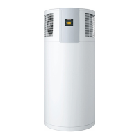
10.6.1 Condensate drain
26_03_01_1127
1
< 35"
1 Condensate drain or
2 Drain pan connected to drain
3 P&T valve
4 Cold water connection
5 Hot water connection
The condensate drain is located in the bottom of the
water heater. This is where you can connect a drain
hose.
When installing the unit outdoors, the condensate can
drain off freely.
For indoor installation, the condensate can be routed
into a floor drain or routed through the wall up to 35"
(see diagram above).
If required, install a condensate pump.
To ensure the condensate drains correctly,
never kink the hose.
10.7 Water connection
The water connection must be carried out by a qualified
licensed plumber.
The cold water connection must comply with DIN1988
[or state and local codes]
» Prior to installing the water heater, flush the line
thoroughly.
H
M
C
26_03_01_1123
1 Vacuum breaker
2 Hot water connection (Union adaptor to 3/4")
3 Mixing valve (supplied by installer)
4 Connection for P&T valve ¾"
5 P&T valve ¾", 100 psi @210 °F (supplied with unit)
6 80 psi relief valve (optional, supplied by installer)
7 Expansion tank (supplied by installer)
8 Straight-through shut-off valve (supplied by
installer)
9 Check valve (supplied by installer)
10 70 psi pressure reduction valve (supplied by
installer)
11 Cold water connection (with Union adaptor to 3/4")
12 Condensate drain (elbow supplied with unit)
13 Drain valve (supplied by installer)
14 Drain pan (supplied by installer)
» Remove the protective rubber caps from the
connectors.
» With a sharp knife, cut a hole into the protective
caps and install them over the pipe to be
connected.
» Connect the plumbing.
2
3
1
4
5
5
6
2
3
4
Cold water
7
8
9
10
Hot water
13
14
12
11

 Loading...