INSTALLATION
Service information
18 | DCE Premium www.stiebeleltronamericas.com
1.
4.
5.
2.
3.
D0000077971
f Undo the screw and disengage the locking tab.
f Push the function module on the back panel gently
backwards.
f Remove the function module from the water heater rear
cover by pulling it slightly forwards and lifting it out.
f Push/break out the required apertures in the back panel
from behind (for positions, see section 17.1, “Dimensions and
connections”, pg. 21). De-burr any sharp edges with a file.
f Install the function module in reverse order onto the water
heater back panel until it clicks into place.
f Secure the function module with the screw.
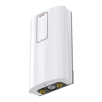
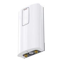
Mounting the water heater
D0000085464-b
21
1 Flat gasket
2 Filter screen with sealed edge
f Mark the 4drill holes, referencing their position on the water
heater rear cover.
f Drill the holes and secure the water heater using suitable
fixing materials (screws and wall anchors are not part of the
standard delivery): Countersunk screw, Ø4.5mm, max. di-
ameter of screw-head 9mm.
f Secure the DHW connection pipe with a flat gasket and the
cold water inlet line with the sealed-edge filter screen (from
the accessories) to the twin connectors.
f Seal the openings on the factory-installed water connections
using the plugs from the accessories.
14. Service information
Connection overview/component overview
D0000077189
1
2
3
4
5
6
7
1 Motorized valve
2 Flow meter
3 High limit safety cut-out, automatic reset
4 NTC sensor
5 Pin strips for connected load and anti-scalding protection
6 Programming unit plug-in position
7 Diagnostic lights
 Loading...