22 | SHD www.stiebel-eltron.com
INSTALLATION
Commissioning
56
7
34
1 2
26�02�07�0096
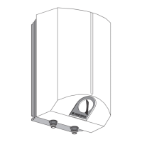
1 Pressure switch for protective anode
2 Operating mode switch
3 Temperature controller
4 Electronic assembly.
5 Contactor
6 Flange plate
7 Seal ring
Select the operating mode using the switch:
Position I = Instantaneous water cylinder mode
Position II = Dual-circuit/single circuit operation
(see chapter "Specification/ Wiring diagrams and connections").
Fit the lower cap.
Insert the screws.
Push on the temperature selector.
Tick the selected connected load and voltage on the type
plate with a ballpoint pen.
Connect the safety assembly to the appliance by screwing the
pipes onto the appliance.
11. Commissioning
11.1 Initial start-up
Open a draw-off point until the appliance has filled up and
the pipework is free of air.
Adjust the flow rate. For this, observe the maximum permis-
sible flow rate with a fully opened tap (see chapter "Specifi-
cation/ Data table").
If necessary reduce the flow rate at the butterfly valve of the
safety valve.
Turn the temperature selector to maximum.
Switch the mains power ON.
Check the function of the appliance. Ensure that the tempera-
ture controller switches off.
Check that the safety valve is working correctly.
11.1.1 Appliance handover
Explain the function of the appliance and safety assembly to
users and familiarise them with their operation.
Make the user aware of potential dangers, especially the risk
of scalding.
Hand over these instructions.
11.2 Recommissioning
See chapter "Commissioning/ Initial start-up".
12. Settings
Limiting the temperature selection
Factory setting: 85°C
Note
You can install a central thermostatic valve at the DHW
outlet if the temperature selection limit is set to 85°C.
This enables the reduction of the outlet temperature.
1
2
3
26�02�07�0099
1 Temperature selector
2 The temperature selection limit can be adjusted to 45°C,
55°C or 65°C.
3 85°C
Set the temperature selection limit.
 Loading...