9
Installation instructions
for approved technicians
Regulations to be observed
– Regulations of the local water utility
company.
– Regulations of the local electricity utility
company.
– Rating plate on the unit.
Operating environment
– Install vertically as shown in Fig. 4.
– The ambient temperature must not be
sub-zero.
– Install as close as possible to the main
water outlet.
Installing the unit
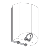
– Attach the wall support to the wall using
the drilling template.
Use the fittings most appropriate to the
consistency of the wall.
Compensate for uneven walls using the
spacers provided (5 mm thick, Fig. 5,
no. 2).
– Slide the protective caps onto the wall
supports (see Fig. 5, no. 3).
Mains water connection
Pressure type fitting for supplying a
number of tap outlets.
– Max. permissible operating pressure
6 bar.
– Install approved safety controls.
– Fit waste pipe to correspond to
maximum possible safety valve opening.
– The safety release waste pipe must be
installed with a downhill inclination. The
safety valve must be regularly inspected
and tested (note the installation instruc-
tions for the safety valve).
– Adjust the coke valve on the safety
group to give a maximum flow rate of
18 L/m. In instantaneous mode a flow
rate of 10 L/m will give a temperature
rise of approx. 28 K.
– During heating, water will drip from the
safety valve. Make sure the end-user is
made aware of this.
– Max. water temperature (supply tank):
Instantaneous hot water
storage operation 25 °C
Dual cycle hot water
storage operation 75 °C
Single cycle hot water
storage operation 75 °C
Instructions de montage
pour l’installateur
Réglementations et normes
applicables
– Réglementation relative aux installations
sanitaires et de plomberie.
– Réglementation relative aux installations
électriques.
– Plaque signalétique.
Lieu de pose
– pose verticale comme indiqué en fig. 4.
– dans une pièce à l’abri du gel.
– à proximité du point de puisage.
Pose de l’appareil
– Fixer le profilé d’accrochage au mur,
pour ce faire utiliser le gabarit de
montage.
– Choisir le matériel de fixation en
fonction de la résistance du mur.
– Compenser les irrégularités du mur au
moyen des cales d’écartement jointes
(épaisseur 5 mm, fig. 5, rep. 2).
– Placer les caches sur les profilés
d’accrochages (fig. 5, rep. 3).
Raccordement hydraulique
Chauffe-eau sous pression (résistant à la
pression) pour alimentation de plusieurs
points de puisage.
– Pression de service admissible: 6 bar.
– Installez des groupes de sécurité
homologués.
KV 30 réf. 00 08 26, pression de la
conduite d’eau jusqu’à 4,8 bar (fig. 9, A)
KV 40 réf. 00 08 28, pression de la
conduite d’eau jusqu’à 10 bar (fig. 9, B)
– Dimensionner la conduite d’évacuation
en fonction de l’ouverture maximale de
la soupape de sûreté.
– La conduite de purge du groupe de
sécurité doit être posée avec une pente.
Le dispositif de sécurité doit être
entretenu et utilisé régulièrement (tenir
compte des instructions fournies dans la
notice de pose du groupe de sécurité).
– Régler le clapet d’étranglement du
groupe de sécurité (KV 30/KV 40) au
débit maxi de 18 l/mn.
A 10 l/mn environ, on obtient en mode
chauffe-eau instantané une augmenta-
tion de température de 28 K.
– Lors de la chauffe, on voit de l’eau
s’échapper de la soupape de sûreté.
Signalez à l’utilisateur que c’est normal.
– Si la soupape de sûreté goutte encore
alors que le chauffage est arrêté, c’est
que la pression d’eau est trop élevée ou
que le siège de la soupape est encrassé.
– température d’eau mai (entrée
accumulateur):
mode accumulation 25 °C
mode accumulation double circuit 75 °C
mode accumulation monocircuit 75 °C
Montagevoorschrift
voor de installateur
Voorschriften en bepalingen
– Bepalingen van de plaatselijke water-
leidingmaatschappij.
– Bepalingen van het plaatselijke energie-
bedrijf.
– Het typeplaatje.
Montageplaats
– Verticaal volgens afb. 4 monteren.
– In een vorstvrije ruimte.
– In de buurt van de kraan monteren.
Montage van het apparaat
– Ophangbeugel monteren. Montage-
sjabloon gebruiken.
Bevestigingsmateriaal afstemmen op de
sterkte van de muur.
Oneffenheden van de muur met de
meegeleverde afstandsstukken (5 mm
dik, afb. 5, pos. 2) compenseren.
– Afschermkapjes op de ophangbeugel
schuiven (afb. 5, pos. 3).
Wateraansluiting
Gesloten (met druk) voor het van warm
water voorzien van diverse kranen.
– Toegestane bedrijfsoverdruk 6 bar.
– Installeer de gekeurde veiligheidsgroepen
KV 30, bestelnr. 00 08 26, tot 4,8 bar
waterleidingdruk (afb. 9, A).
KV 40, bestelnr. 00 08 28, tot 10 bar
waterleidingdruk (afb. 9, B).
– Afvoerleiding moet groot genoeg zijn
voor volledig geopend veiligheidsventiel.
Afvoerleiding dient altijd open te blijven.
– De afblaasleiding van de veiligheidsgroep
moet aflopend geïnstalleerd zijn.
Regelmatig onderhoud en regelmatig
controleren van de veiligheids-
voorziening is noodzakelijk – de
aanwijzingen in het montagevoorschrift
voor de veiligheidsgroep moeten in acht
genomen worden).
– Doorstroomhoeveelheid van max.
18 l/min op het reduceerventiel van de
veiligheidsgroep instellen.
Bij ca. 10 l/min. wordt in de geiserfunctie
een temperatuurverhoging van 28 K
bereikt.
– Bij opwarming komt zichtbaar water uit
het veiligheidsventiel. Maak de gebruikers
hierop attent.
– Indien het veiligheidsventiel druppelt
terwijl de elementen uitgeschakeld zijn,
is de waterdruk te hoog of de klepzitting
vuil.
– Max. watertemperatuur
(toevoerreservoir):
Doorstroom-boilerfunctie 25 °C
Duoboilerfunctie 75 °C
Monoboilerfunctie 75 °C
English Français
Nederlands
 Loading...